- ES - Home
- ES - Overview
- ES - Processors
- ES - Architectures
- ES - Tools and Peripherals
- ES - 8051 Microcontroller
- ES - I/O Programming
- ES - Terms
- ES - Assembly Language
- ES - Registers
- ES - Registers Bank/Stack
- ES - Instructions
- ES - Addressing Modes
- ES - Special Function Registers
- ES - Timer/Counter
- ES - Interrupts
Embedded Systems - Interrupts
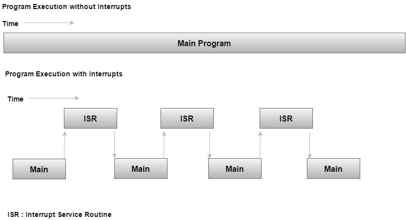
An interrupt is a signal to the processor emitted by hardware or software indicating an event that needs immediate attention. Whenever an interrupt occurs, the controller completes the execution of the current instruction and starts the execution of an Interrupt Service Routine (ISR) or Interrupt Handler. ISR tells the processor or controller what to do when the interrupt occurs. The interrupts can be either hardware interrupts or software interrupts.
Hardware Interrupt
A hardware interrupt is an electronic alerting signal sent to the processor from an external device, like a disk controller or an external peripheral. For example, when we press a key on the keyboard or move the mouse, they trigger hardware interrupts which cause the processor to read the keystroke or mouse position.
Software Interrupt
A software interrupt is caused either by an exceptional condition or a special instruction in the instruction set which causes an interrupt when it is executed by the processor. For example, if the processor's arithmetic logic unit runs a command to divide a number by zero, to cause a divide-by-zero exception, thus causing the computer to abandon the calculation or display an error message. Software interrupt instructions work similar to subroutine calls.
What is Polling?
The state of continuous monitoring is known as polling. The microcontroller keeps checking the status of other devices; and while doing so, it does no other operation and consumes all its processing time for monitoring. This problem can be addressed by using interrupts.
In the interrupt method, the controller responds only when an interruption occurs. Thus, the controller is not required to regularly monitor the status (flags, signals etc.) of interfaced and inbuilt devices.
Interrupts v/s Polling
Here is an analogy that differentiates an interrupt from polling −
| Interrupt | Polling |
|---|---|
| An interrupt is like a shopkeeper. If one needs a service or product, he goes to him and apprises him of his needs. In case of interrupts, when the flags or signals are received, they notify the controller that they need to be serviced. | The polling method is like a salesperson. The salesman goes from door to door while requesting to buy a product or service. Similarly, the controller keeps monitoring the flags or signals one by one for all devices and provides service to whichever component that needs its service. |
Interrupt Service Routine
For every interrupt, there must be an interrupt service routine (ISR), or interrupt handler. When an interrupt occurs, the microcontroller runs the interrupt service routine. For every interrupt, there is a fixed location in memory that holds the address of its interrupt service routine, ISR. The table of memory locations set aside to hold the addresses of ISRs is called as the Interrupt Vector Table.
Interrupt Vector Table
There are six interrupts including RESET in 8051.
| Interrupts | ROM Location (Hex) | Pin |
|---|---|---|
| Interrupts | ROM Location (HEX) | |
| Serial COM (RI and TI) | 0023 | |
| Timer 1 interrupts(TF1) | 001B | |
| External HW interrupt 1 (INT1) | 0013 | P3.3 (13) |
| External HW interrupt 0 (INT0) | 0003 | P3.2 (12) |
| Timer 0 (TF0) | 000B | |
| Reset | 0000 | 9 |
When the reset pin is activated, the 8051 jumps to the address location 0000. This is power-up reset.
Two interrupts are set aside for the timers: one for timer 0 and one for timer 1. Memory locations are 000BH and 001BH respectively in the interrupt vector table.
Two interrupts are set aside for hardware external interrupts. Pin no. 12 and Pin no. 13 in Port 3 are for the external hardware interrupts INT0 and INT1, respectively. Memory locations are 0003H and 0013H respectively in the interrupt vector table.
Serial communication has a single interrupt that belongs to both receive and transmit. Memory location 0023H belongs to this interrupt.
Steps to Execute an Interrupt
When an interrupt gets active, the microcontroller goes through the following steps −
The microcontroller closes the currently executing instruction and saves the address of the next instruction (PC) on the stack.
It also saves the current status of all the interrupts internally (i.e., not on the stack).
It jumps to the memory location of the interrupt vector table that holds the address of the interrupts service routine.
The microcontroller gets the address of the ISR from the interrupt vector table and jumps to it. It starts to execute the interrupt service subroutine, which is RETI (return from interrupt).
Upon executing the RETI instruction, the microcontroller returns to the location where it was interrupted. First, it gets the program counter (PC) address from the stack by popping the top bytes of the stack into the PC. Then, it start to execute from that address.
Edge Triggering vs. Level Triggering
Interrupt modules are of two types − level-triggered or edge-triggered.
| Level Triggered | Edge Triggered |
|---|---|
| A level-triggered interrupt module always generates an interrupt whenever the level of the interrupt source is asserted. | An edge-triggered interrupt module generates an interrupt only when it detects an asserting edge of the interrupt source. The edge gets detected when the interrupt source level actually changes. It can also be detected by periodic sampling and detecting an asserted level when the previous sample was de-asserted. |
| If the interrupt source is still asserted when the firmware interrupt handler handles the interrupt, the interrupt module will regenerate the interrupt, causing the interrupt handler to be invoked again. | Edge-triggered interrupt modules can be acted immediately, no matter how the interrupt source behaves. |
| Level-triggered interrupts are cumbersome for firmware. | Edge-triggered interrupts keep the firmware's code complexity low, reduce the number of conditions for firmware, and provide more flexibility when interrupts are handled. |
Enabling and Disabling an Interrupt
Upon Reset, all the interrupts are disabled even if they are activated. The interrupts must be enabled using software in order for the microcontroller to respond to those interrupts.
IE (interrupt enable) register is responsible for enabling and disabling the interrupt. IE is a bitaddressable register.
Interrupt Enable Register
| EA | - | ET2 | ES | ET1 | EX1 | ET0 | EX0 |
|---|
EA − Global enable/disable.
- − Undefined.
ET2 − Enable Timer 2 interrupt.
ES − Enable Serial port interrupt.
ET1 − Enable Timer 1 interrupt.
EX1 − Enable External 1 interrupt.
ET0 − Enable Timer 0 interrupt.
EX0 − Enable External 0 interrupt.
To enable an interrupt, we take the following steps −
Bit D7 of the IE register (EA) must be high to allow the rest of register to take effect.
If EA = 1, interrupts will be enabled and will be responded to, if their corresponding bits in IE are high. If EA = 0, no interrupts will respond, even if their associated pins in the IE register are high.
Interrupt Priority in 8051
We can alter the interrupt priority by assigning the higher priority to any one of the interrupts. This is accomplished by programming a register called IP (interrupt priority).
The following figure shows the bits of IP register. Upon reset, the IP register contains all 0's. To give a higher priority to any of the interrupts, we make the corresponding bit in the IP register high.
| - | - | - | - | PT1 | PX1 | PT0 | PX0 |
|---|
| - | IP.7 | Not Implemented. |
| - | IP.6 | Not Implemented. |
| - | IP.5 | Not Implemented. |
| - | IP.4 | Not Implemented. |
| PT1 | IP.3 | Defines the Timer 1 interrupt priority level. |
| PX1 | IP.2 | Defines the External Interrupt 1 priority level. |
| PT0 | IP.1 | Defines the Timer 0 interrupt priority level. |
| PX0 | IP.0 | Defines the External Interrupt 0 priority level. |
Interrupt inside Interrupt
What happens if the 8051 is executing an ISR that belongs to an interrupt and another one gets active? In such cases, a high-priority interrupt can interrupt a low-priority interrupt. This is known as interrupt inside interrupt. In 8051, a low-priority interrupt can be interrupted by a high-priority interrupt, but not by any another low-priority interrupt.
Triggering an Interrupt by Software
There are times when we need to test an ISR by way of simulation. This can be done with the simple instructions to set the interrupt high and thereby cause the 8051 to jump to the interrupt vector table. For example, set the IE bit as 1 for timer 1. An instruction SETB TF1 will interrupt the 8051 in whatever it is doing and force it to jump to the interrupt vector table.
