- Linear Wave Shapping
- Special Functions of LPF and HPF
- Nonlinear Wave Shapping
- Positive Clipper Circuits
- Negative Clipper Circuits
- Clamper Circuits
- Limiter & Voltage Multiplier
- Diode as a Switch
- Power Supplies
- Power Supplies
- Electronic Circuits - Rectifiers
- Full Wave Rectifiers
- Electronic Circuits - Filters
- Electronic Circuits - Regulators
- Electronic Circuits - SMPS
- Electronic Circuits Resources
- Electronic Circuits - Quick Guide
- Electronic Circuits - Resources
- Electronic Circuits - Discussion
Electronic Circuits - SMPS
The topics discussed till now represent different sections of power supply unit. All these sections together make the Linear Power Supply. This is the conventional method of obtaining DC out of the input AC supply.
Linear Power Supply
The Linear Power Supply (LPS) is the regulated power supply which dissipates much heat in the series resistor to regulate the output voltage which has low ripple and low noise. This LPS has many applications.
A linear power supply requires larger semiconductor devices to regulate the output voltage and generates more heat resulting in lower energy efficiency. Linear power supplies have transient response times up to 100 times faster than the others, which is very important in certain specialized areas.
Advantages of LPS
- The power supply is continuous.
- The circuitry is simple.
- These are reliable systems.
- This system dynamically responds to load changes.
- The circuit resistances are changed to regulate the output voltage.
- As the components operate in linear region, the noise is low.
- The ripple is very low in the output voltage.
Disadvantages of LPS
- The transformers used are heavier and large.
- The heat dissipation is more.
- The efficiency of linear power supply is 40 to 50%
- Power is wasted in the form of heat in LPS circuits.
- Single output voltage is obtained.
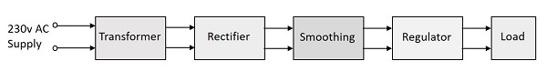
We have already gone through different parts of a Linear Power supply. The block diagram of a Linear Power Supply is as shown in the following figure.
In spite of the above disadvantages, Linear Power Supplies are widely used in low-noise amplifiers, test equipment, control circuits. In addition, they are also used in data acquisition and signal processing.
All the power supply systems that needs simple regulation and where efficiency is not a concern, the LPS circuits are used. As the electrical noise is lower, the LPS is used in powering sensitive analog circuitry. But to overcome the disadvantages of Linear Power Supply system, the Switched Mode Power Supply (SMPS) is used.
Switched Mode Power Supply (SMPS)
The disadvantages of LPS such as lower efficiency, the need for large value of capacitors to reduce ripples and heavy and costly transformers etc. are overcome by the implementation of Switched Mode Power Supplies.
The working of SMPS is simply understood by knowing that the transistor used in LPS is used to control the voltage drop while the transistor in SMPS is used as a controlled switch.
Working
The working of SMPS can be understood by the following figure.
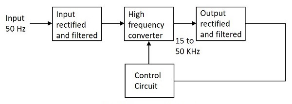
Let us try to understand what happens at each stage of SMPS circuit.
Input Stage
The AC input supply signal 50 Hz is given directly to the rectifier and filter circuit combination without using any transformer. This output will have many variations and the capacitance value of the capacitor should be higher to handle the input fluctuations. This unregulated dc is given to the central switching section of SMPS.
Switching Section
A fast switching device such as a Power transistor or a MOSFET is employed in this section, which switches ON and OFF according to the variations and this output is given to the primary of the transformer present in this section. The transformer used here are much smaller and lighter ones unlike the ones used for 60 Hz supply. These are much efficient and hence the power conversion ratio is higher.
Output Stage
The output signal from the switching section is again rectified and filtered, to get the required DC voltage. This is a regulated output voltage which is then given to the control circuit, which is a feedback circuit. The final output is obtained after considering the feedback signal.
Control Unit
This unit is the feedback circuit which has many sections. Let us have a clear understanding about this from The following figure.
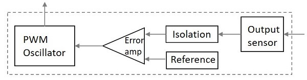
The above figure explains the inner parts of a control unit. The output sensor senses the signal and joins it to the control unit. The signal is isolated from the other section so that any sudden spikes should not affect the circuitry. A reference voltage is given as one input along with the signal to the error amplifier which is a comparator that compares the signal with the required signal level.
By controlling the chopping frequency the final voltage level is maintained. This is controlled by comparing the inputs given to the error amplifier, whose output helps to decide whether to increase or decrease the chopping frequency. The PWM oscillator produces a standard PWM wave fixed frequency.
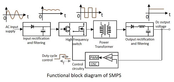
We can get a better idea on the complete functioning of SMPS by having a look at the following figure.
The SMPS is mostly used where switching of voltages is not at all a problem and where efficiency of the system really matters. There are few points which are to be noted regarding SMPS. They are
SMPS circuit is operated by switching and hence the voltages vary continuously.
The switching device is operated in saturation or cut off mode.
The output voltage is controlled by the switching time of the feedback circuitry.
Switching time is adjusted by adjusting the duty cycle.
The efficiency of SMPS is high because, instead of dissipating excess power as heat, it continuously switches its input to control the output.
Disadvantages
There are few disadvantages in SMPS, such as
- The noise is present due to high frequency switching.
- The circuit is complex.
- It produces electromagnetic interference.
Advantages
The advantages of SMPS include,
- The efficiency is as high as 80 to 90%
- Less heat generation; less power wastage.
- Reduced harmonic feedback into the supply mains.
- The device is compact and small in size.
- The manufacturing cost is reduced.
- Provision for providing the required number of voltages.
Applications
There are many applications of SMPS. They are used in the motherboard of computers, mobile phone chargers, HVDC measurements, battery chargers, central power distribution, motor vehicles, consumer electronics, laptops, security systems, space stations, etc.
Types of SMPS
SMPS is the Switched Mode Power Supply circuit which is designed for obtaining the regulated DC output voltage from an unregulated DC or AC voltage. There are four main types of SMPS such as
- DC to DC Converter
- AC to DC Converter
- Fly back Converter
- Forward Converter
The AC to DC conversion part in the input section makes the difference between AC to DC converter and DC to DC converter. The Fly back converter is used for Low power applications. Also there are Buck Converter and Boost converter in the SMPS types which decrease or increase the output voltage depending upon the requirements. The other type of SMPS include Self-oscillating fly-back converter, Buck-boost converter, Cuk, Sepic, etc.
