- Linear Wave Shapping
- Special Functions of LPF and HPF
- Nonlinear Wave Shapping
- Positive Clipper Circuits
- Negative Clipper Circuits
- Clamper Circuits
- Limiter & Voltage Multiplier
- Diode as a Switch
- Power Supplies
- Power Supplies
- Electronic Circuits - Rectifiers
- Full Wave Rectifiers
- Electronic Circuits - Filters
- Electronic Circuits - Regulators
- Electronic Circuits - SMPS
- Electronic Circuits Resources
- Electronic Circuits - Quick Guide
- Electronic Circuits - Resources
- Electronic Circuits - Discussion
Limiter and Voltage Multiplier
Along with the wave shaping circuits such as clippers and clampers, diodes are used to construct other circuits such as limiters and voltage multipliers, which we shall discuss in this chapter. Diodes also have another important application known as rectifiers, which will be discussed later.
Limiters
Another name which we often come across while going through these clippers and clampers is the limiter circuit. A limiter circuit can be understood as the one which limits the output voltage from exceeding a pre-determined value.
This is more or less a clipper circuit which does not allow the specified value of the signal to exceed. Actually clipping can be termed as an extreme extent of limiting. Hence limiting can be understood as a smooth clipping.
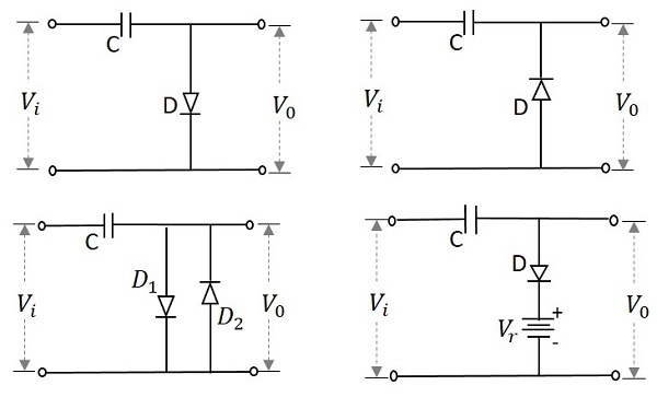
The following image shows some examples of limiter circuits −
The performance of a limiter circuit can be understood from its transfer characteristic curve. An example for such a curve is as follows.
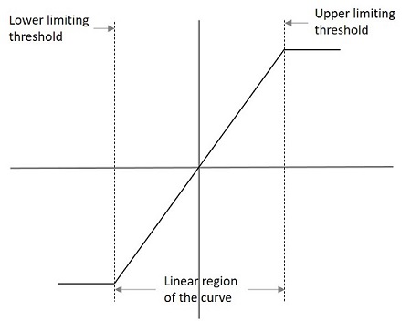
The lower and upper limits are specified in the graph which indicate the limiter characteristics. The output voltage for such a graph can be understood as
$$V_{0}= L_{-},KV_{i},L_{+}$$
Where
$$L_{-}=V_{i}\leq \frac{L_{-}}{k}$$
$$KV_{i}=\frac{L_{-}}{k}
$$L_{+}=V_{i}\geq \frac{L_{+}}{K}$$
Types of Limiters
There are few types of limiters such as
Unipolar Limiter − This circuit limits the signal in one way.
Bipolar Limiter − This circuit limits the signal in two way.
Soft Limiter − The output may change in this circuit for even a slight change in the input.
Hard Limiter − The output will not easily change with the change in input signal.
Single Limiter − This circuit employs one diode for limiting.
Double Limiter − This circuit employs two diodes for limiting.
Voltage Multipliers
There are applications where the voltage needs to be multiplied in some cases. This can be done easily with the help of a simple circuit using diodes and capacitors. The voltage if doubled, such a circuit is called as a Voltage Doubler. This can be extended to make a Voltage Tripler or a Voltage Quadrupler or so on to obtain high DC voltages.
To get a better understanding, let us consider a circuit that multiplies the voltage by a factor of 2. This circuit can be called as a Voltage Doubler. The following figure shows the circuit of a voltage doubler.
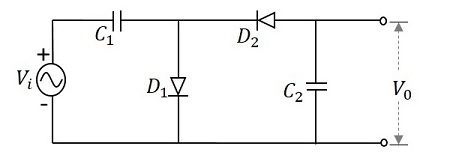
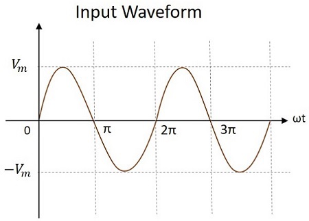
The input voltage applied will be an AC signal which is in the form of a sine wave as shown in the figure below.
Working
The voltage multiplier circuit can be understood by analyzing each half cycle of the input signal. Each cycle makes the diodes and the capacitors work in different fashion. Let us try to understand this.
During the first positive half cycle − When the input signal is applied, the capacitor $C_{1}$ is charged and the diode $D_{1}$ is forward biased. While the diode $D_{2}$ is reverse biased and the capacitor $C_{2}$ doesnt get any charge. This makes the output $V_{0}$ to be $V_{m}$
This can be understood from the following figure.
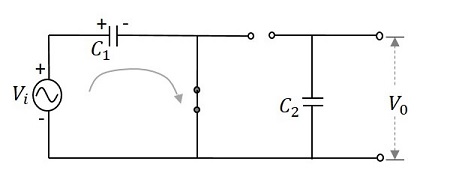
Hence, during 0 to $\pi$, the output voltage produced will be $V_{max}$. The capacitor $C_{1}$ gets charged through the forward biased diode $D_{1}$ to give the output, while $C_{2}$ doesnt charge. This voltage appears at the output.
During the negative half cycle − After that, when the negative half cycle arrives, the diode $D_{1}$ gets reverse biased and the diode $D_{2}$ gets forward biased. The diode $D_{2}$ gets the charge through the capacitor $C_{2}$ which gets charged during this process. The current then flows through the capacitor $C_{1}$ which discharges. It can be understood from the following figure.
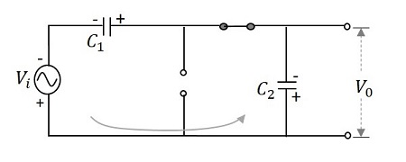
Hence during $\pi$ to $2\pi$, the voltage across the capacitor $C_{2}$ will be $V_{max}$. While the capacitor $C_{1}$ which is fully charged, tends to discharge. Now the voltages from both the capacitors together appear at the output, which is $2V_{max}$. So, the output voltage $V_{0}$ during this cycle is $2V_{max}$
During the next positive half cycle − The capacitor $C_{1}$ gets charged from the supply and the diode $D_{1}$ gets forward biased. The capacitor $C_{2}$ holds the charge as it will not find a way to discharge and the diode $D_{2}$ gets reverse biased. Now, the output voltage $V_{0}$ of this cycle gets the voltages from both the capacitors that together appear at the output, which is $2V_{max}$.
During the next negative half cycle − The next negative half cycle makes the capacitor $C_{1}$ to again discharge from its full charge and the diode $D_{1}$ to reverse bias while $D_{2}$ forward and capacitor $C_{2}$ to charge further to maintain its voltage. Now, the output voltage $V_{0}$ of this cycle gets the voltages from both the capacitors that together appear at the output, which is $2V_{max}$.
Hence, the output voltage $V_{0}$ is maintained to be $2V_{max}$ throughout its operation, which makes the circuit a voltage doubler.
Voltage multipliers are mostly used where high DC voltages are required. For example, cathode ray tubes and computer display.
Voltage Divider
While diodes are used to multiply the voltage, a set of series resistors can be made into a small network to divide the voltage. Such networks are called as Voltage Divider networks.
Voltage divider is a circuit which turns a larger voltage into a smaller one. This is done using resistors connected in series. The output will be a fraction of the input. The output voltage depends upon the resistance of the load it drives.
Let us try to know how a voltage divider circuit works. The figure below is an example of a simple voltage divider network.
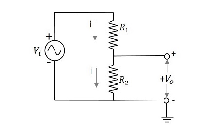
If we try to draw an expression for output voltage,
$$V_{i}=i\left ( R_{1}+R_{2} \right )$$
$$i=\frac{V-{i}}{\left ( R_{1}+R_{2} \right )}$$
$$V_{0}=i \:R_{2}\rightarrow \:i\:=\frac{V_{0}}{R_{2}}$$
Comparing both,
$$\frac{V_{0}}{R_{2}}=\frac{V_{i}}{\left ( R_1 + R_{2} \right )}$$
$$V_{0}=\frac{V_{i}}{\left ( R_1 + R_{2} \right )}R_{2}$$
This is the expression to obtain the value of output voltage. Hence the output voltage is divided depending upon the resistance values of the resistors in the network. More resistors are added to have different fractions of different output voltages.
Let us have an example problem to understand more about voltage dividers.
Example
Calculate the output voltage of a network having an input voltage of 10v with two series resistors 2k and 5k.
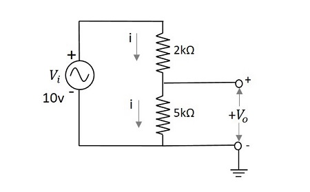
The output voltage $V_{0}$ is given by
$$V_{0}=\frac{V_{i}}{\left ( R_1 + R_{2} \right )}R_{2}$$
$$=\frac{10}{\left ( 2 + 5 \right )k\Omega }5k\Omega$$
$$=\frac{10}{7}\times 5=\frac{50}{7}$$
$$=7.142v$$
The output voltage $V_0$ for the above problem is 7.14v
