- Electrical Safety - Home
- Power System
- Indian Standards
- Low Voltage Overload Protection
- Short Circuit Protection
- Earth Fault Protection
- Earthing
- Types of the Supply System
- Cables
- Classification of Hazard-Prone Areas
- Safety Measures Related to Gas/Ducts/Fibre material
- Classification of Temperature
- Protection Against Weather Complexities
- Safe Electrical Equipment Design Characteristics
- Test Certifications
- Procedure to Mark Unprotected Equipment
- Maintenance of Unprotected Equipment
- Duties and Obligations
- Primary Ex-protection
- Secondary Ex-Protection
- Precautions Against Highly Flammable Contents
- Safety Measures During Handling Lighting Protection Equipment
- Bonding
- Transformer Safety
- Motor Handling Safety
- Generator Handling Safety
- Crane Handling Safety
- Safety Measures During Preventive Maintenance
- Types of Safety Equipment
- Implications of Human Behaviour
- Do's and Don'ts at a Glance
Electrical Safety - Quick Guide
Electrical Safety - Power System
The power system consists of a three-stage network generation, distribution, and transmission. The power system is responsible for the production of electricity with the help of energy such as coal and diesel. All the devices connected to the system such as a motor, circuit breaker, transformer, etc., fall under the umbrella of a power system.
Components of a Power System
There are six main components of a power system. Let us see what the components are −
The Power Plant
The place where power is generated and set for transmitted with the help of a transformer.
Transformer
Transmit electrical energy from one circuit to another.
Transmission Line
The power passes through the transmission line towards the substations.
Substation
Power is transferred to the distribution line through a medium.
Distribution Line
It comprises of low and medium level power lines that connect to the distribution transformer.
Distribution Transformer
From the distribution line, the electricity is distributed to consumers as per an appropriate value.
Causes of Hazards
Electrical hazards are recorded in thousands of number per year, which includes more than 30 fatality cases. Therefore, it is essential to stay away from electrical hazards.
Several factors lead to electricity hazards. The factors are described below in brief −
Faulty wiring
Exposure to loose, frayed and naked wires possess a severe health risk. It is the responsibility of the worker to report cases for damage or faulty cable to the authority as soon as possible. The best way to avoid risk is to inform everyone about it and never try to deal if one is not legally authorized.
Improper usage of equipment
Practicing a safety approach for using electrical equipment is imperative. If a worker is not permitted and trained to use a particular electrical device, then he/she should avoid using it. Sometimes live equipment can seem dead and can cause a severe fatality. A worker should also avoid using electrical tools when on a suspended platform unless he/she is entitled to it.
Overused outlets
All electrical outlets have thresholds. After usage, an outlet starts to fray and poses a risk. When overused, an outlet begins to overheat or generates less power than usual. If a worker experiences an overheating or sparks from an outlet, then he/she must inform the authority rather than dealing with it him/herself.
Exposure to liquid
Water and all other liquids are a good conductor of electricity. Therefore, all workers should always try to keep their electrical equipment away from any liquid. Also, while using electric equipment, all workers must pat their hands dry to avoid any shock or burn.
Need for safety
Electrical hazards are something that should be taken seriously in a workplace. Every organization has to conduct an electrical safety programme for all their workers. Apart from informing them about the hazards, the workers should also take a safety workshop.
Many workers in a workplace do not pay much heed towards electricity hazards. Some think that electrical related incidents are a part of life and some even believe that accidents can never happen to them. What makes it worse is that, some workers think that health risk is a part of their job and it cannot be avoided. Such type of careless attitude among employees results in more work-related injuries. To bring effective changes in workers perspective, a safety program is of paramount importance.
Electrical Safety - Indian Standards
In the field of electrical engineering, engineers and other professionals get exposed to electricity indirectly during generation, transportation, installation and usage. Such conditions might cause hazards if accurate safety measures are not taken.
To promote the safety and the right usage of equipment, there are certain rules and regulations formulated by the Bureau of Indian Standards (BIS). BIS follows the following five principles −
- Safety
- Ease of use and adaptability
- Simple technology
- Value for money products
- Energy efficiency and environment
BIS has published the following code of practice for public safety standards in order to promote the right to information, transparency and accountability in a proper manner to the public.
Code of Practice for Electrical Wiring Installation
IS − 732 (1989)
Section − Electrical Installation
Application − Design of installation, selection and erection of equipment, inspection and testing of wiring system
Code of practice for Earthing
IS − 3043 (1987)
Section − Electrical Installation
Application − Design, installation and calculation of Earthing system
Lightning arrester for Alternating Current System
IS − 3070 (1993)
Section − Electro technical: Surge Arresters
Application − Identification, ratings, classification and testing procedure of Arrester
Let us now consider other important codes of practice established by BIS for the purpose of electrification. The codes are listed in the table below −
| General Requirements | |
|---|---|
| Sr. No. | Standards & Application |
| 1 | IS:900 Installation and maintenance of Induction motors |
| 2 | IS:1271 Classification of insulating materials for electrical machinery |
| 3 | IS:1646 Fire safety of buildings (general) electrical installation |
| 4 | IS:1882 Outdoor installation of Public Address System (PAS) |
| 5 | IS:1886 Installation and maintenance of Transformers |
| 6 | IS:1913 General and safety requirements of electric lighting fittings |
| 7 | IS:2032 Graphical symbols related to electrical technology |
| 8 | IS:2274 Electrical wiring installations where system voltage is more than 658 volts |
| 9 | IS:3034 Fire safety of industrial buildings (Electrical generation and distribution stations) |
| 10 | IS:3072 (part-1) Installation and maintenance of switchgear where system voltage is less than 1000 volts |
| 11 | IS:3106 Selection, installation and maintenance of fuse where system voltage is less than 650 volts |
| 12 | IS:3638 Guide for gas operated relays |
| 13 | IS:3646 Practice for interior illumination |
| 14 | IS:3716 Guide for insulation coordination |
| 15 | IS:3842 Guide for electrical relays for AC system |
| 16 | IS:4004 Guide for lightening arrestors (non-linear ) for AC system |
| 17 | IS:4146 Guide for voltage transformers |
| 18 | IS:4201 Guide for current transformers |
| 19 | IS:5571 Selection of electrical equipment in hazardous area |
| 20 | IS:5572 Types of hazardous areas for electrical installations |
| 21 | IS:5780 Intrinsically safe electrical apparatus and circuit |
| 22 | IS:5908 Measurement of electrical installations in buildings |
Switchgear
The following table lists down the codes of practice for the maintenance of switchgear −
| General Requirements | |
|---|---|
| Sr. No. | Standards & Application |
| 1 | IS:375 Making and arrangement for switchgear bus-bars, main connections and auxiliary winding |
| 2 | IS:694(part-1) PVC insulating cables with copper conductors (where voltage is up to 100v) |
| 3 | IS:1248 Direct acting electrical indicating instruments |
| 4 | IS:2147 Degrees of protections for enclosures for switchgear and control gear (low voltage) |
| 5 | IS:2208 Guide for HRC fuse (up to 650v) |
| 6 | IS:3202 Guide for climate proofing of electrical equipment |
| 7 | IS:3231 Guide for electrical relays of power system protection |
| 8 | IS:4047 Guide for heavy duty air break switches and fuses for voltage less than 1000v |
| 9 | IS:4237 Requirements for switchgears and control gears for voltage up to 1000v |
| 10 | IS:5987 Selection of switches where voltage is up to 1000v |
| 11 | IS:335 Insulating oil for transformers and switch gear |
| 12 | IS:2516(part-1,sec-2) AC circuit breakers (Tests for the voltage range 1000v to 11000v) |
| 13 | IS:3427 Metal enclosed switch gear and control gear for voltage within 1000v to 11000v |
| 14 | IS:722 AC electricity meters for 415 volts |
| 15 | IS:1951 PVC sleeving for electrical works |
| 16 | IS:2516(part-1sec-1 & part-2sec2) AC circuit breaker (Tests for voltage within 1000v) |
| 17 | IS:2419 Guide for dimension of electrical indicating instruments |
Motor Control Centre (MCC)
The following table lists down the codes of practice for the maintenance of Motor Control Centre −
| General Requirements | |
|---|---|
| Sr. No. | Standards & Application |
| 1 | IS:1554(part-1) PVC insulated heavy duty electric cables for the voltage up to 1100v |
| 2 | IS:1822 AC motor starters of voltage less than 1000v |
| 3 | IS:2959 AC contactors of voltage less than 1000v |
| 4 | IS:3961(part-2) Recommended current ratings for PVC insulated and PVC sheathed cables |
| 5 | IS:5124 Installation and maintenance of AC induction motor starters within 1000v |
| 6 | IS:2959 Guide for AC contactors of voltage less than 1000v |
Invertors
The following table lists down the codes of practice for the maintenance of invertors −
| General Requirements | |
|---|---|
| Sr. No. | Standards & Application |
| 1 | IS:391 Mains transformers for electronic equipment |
Transformers
The following table lists down the codes of practice for the maintenance of transformers −
| General Requirements | |
|---|---|
| Sr. No. | Standards & Application |
| 1 | IS:335 Insulating oil for transformer and switch gear |
| 2 | IS:2026 Power transformers |
| 3 | IS:2099 High voltage porcelain bushings |
| 4 | IS:3637 Gas operated relays |
| 5 | IS:3639 Fitting and accessories for power transformers |
Motors
The following table lists down the codes of practice for the maintenance of motors −
| General Requirements | |
|---|---|
| Sr. No. | Standards & Application |
| 1 | IS:325 3-ph induction motors |
| 2 | IS:4691 Degrees of protection provided by enclosures for rotating machinery |
| 3 | IS:4722 Guide for rotating electrical machines |
Batteries
The following table lists down the codes of practice for the maintenance of batteries −
| General Requirements | |
|---|---|
| Sr. No. | Standards & Application |
| 1 | IS:1652 Guide for stationery cells and batteries, lead-acid type with plante positive plates |
Cables
The following table lists down the codes of practice for the maintenance of cables −
| General Requirements | |
|---|---|
| Sr. No. | Standards & Application |
| 1 | IS:1753 Aluminum conductors for insulated cables |
| 2 | IS:3961(part-2) Guide for current ratings for cable |
| 3 | IS:3975 Guide for mild steel wires, strips and tapes for armouring cables |
| 4 | IS:5819 Guide for short circuit ratings of high voltage cables |
| 5 | IS:5831 Guide for PVC insulation and sheath of electric cables |
Alternators
The following table lists down the codes of practice for the maintenance of alternators −
| General Requirements | |
|---|---|
| Sr. No. | Standards & Application |
| 1 | IS:7132 Guide for testing synchronous machines |
| 2 | IS:5422 Guide for turbine type generators |
| 3 | IS:7306 Methods for determining synchronous machine quantities |
Low Voltage Overload Protection
We will now learn the different concepts related to low voltage overload protection.
Low Voltage Release
If the line voltage decreases to an abnormally low value, then the electrical machinery is damaged or unable to start the service. Because of the low voltage, the shunt coil on final contact holding solenoid of the starter disconnects the motor from the line. After the line voltage recovery the motor resumes its service. Low voltage release is unexpected and dangerous. To protect the machines, low voltage protection should be provided.
Low Voltage Over-current Fault
In low voltage condition, the protection against temperature is known as over-current protection. There are three major causes of over-current. The causes are listed below −
By equipment overload
The overload condition occurs when equipment is subjected to more than its rated value. This results in excessive heat production.
By short circuits
If there is any connection between the line to line or line to neutral conductors, it leads to short circuit. This generates temperature above the designated ratings.
By ground faults
If the electrical current flows from a conductor to uninsulated metal, then ground fault occurs.
Overload Protection
The current flows in the circuit based on the demand of loads. If the amount of current increases and exceeds the rating of the electrical equipment, then the system is overloaded. The wires or cables may not with withstand the higher current. The wires get hot and even melt the insulation. This leads to fire hazards. Therefore, overload protection is necessary to avoid such accidents.
Causes of Overload Condition
Following are the different causes of overload condition −
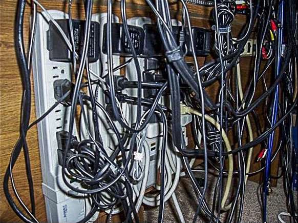
Overuse of extension cords and multiple plug adapters on the same circuit.
Running too many appliances at a time.
When more electricity is used like electric decoration.
The following image shows the overuse of extension cord −
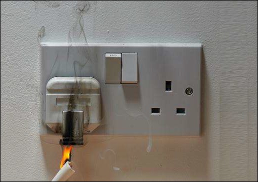
The following image shows how a fire hazard is triggered due to overloading −
Signs of Low Voltage Overloading
Let us now see the different signs of low voltage overloading. Following are the different signs −
- Flickering of lights
- Sparks from appliances or wall sockets
- Warm switch plates
- Dimming of lights, television sets
- Speed reduction of motors
To avoid such problems, fuse and miniature circuit breakers are used as protecting devices. In fault condition, the fuse should blow and circuit breaker should open the circuit. It is also important to protect the conductors as well as equipment from the higher current.
Conductor Protection
Every cable has a current rating, which is the maximum safe current capacity of the cable. This current carrying capacity depends on the following factors −
Material − Aluminum or Copper
A structure − Individual conductor or grouped conductors
Path medium − Open air, grounded, or near the hot furnace or inside well-ventilated room, etc.
The fuse or breaker should be chosen based on the size of the cable. When the fault current reaches the fuse, it will blow. This gives a temporary overload condition to the cable. The cable must carry momentary overloads for a very short time period. A small amount of overheating cannot build a dangerous level. This is called slow blow protector.
Equipment Protection
The fuse and circuit breaker can protect the cable. However, these are not sensitive to protect a small use device plugged into the circuit. Therefore, these protection devices are built into the appliances to protect from overload. The external fuses are used in the main service panels or sub-panels but the equipment fuse or breakers protect every part of the electrical equipment that secures the system.
The following image shows the thermal fuse inside a motor −

Electrical Safety - Short Circuit Protection
A short-circuit condition means a circuit allows the current to flow through an unintended path with very low electrical impedance. It is a direct contact between two points of different electric potential.
The short circuit protection system is broken down into the following systems −
Alternating Current System
- Phase to Ground contact
- Phase to Neutral contact
- Phase to Phase contact
- Contact between windings of an electrical machine in a phase
Direct Current System
- Pole to Ground contact
- Contact between two poles
There can be numerous causes resulting in the above type of contacts including damage to the insulation of conductors, loose, broken or stripped wires and cables, and deposition of conducting materials such as dust, moisture, etc.
Major Causes of Short Circuit
A sudden surge of current equals to hundred times of working current flows through the circuit. This leads to the damage of electrical equipment. The following two phenomena are responsible for the devastating effects of short circuits −
Thermal Phenomenon
This phenomenon refers to the energy released into the electrical circuit when short-circuiting current flows through the circuit. This thermal effect results in the causes of a short circuit −
Melting of the conductor contacts
Damage to insulation
Generation of electrical arcs
Destruction of the thermal elements in the bimetallic relay
Electro-dynamic Phenomenon
This phenomenon refers to the production of intensive mechanical stress when the current crosses and results in the following conditions −
- Breakage of the conductors
- Repulsion of contacts inside the contactors
- Distortion of conductors in windings
Short Circuit Protection Devices
To protect the devices and people from short circuit hazards, protecting devices are used in electrical circuits. These devices can detect the faults and trip the circuit immediately before the surge current reaches to the maximum.
There are two popular protecting devices used frequently in every electrical circuit.
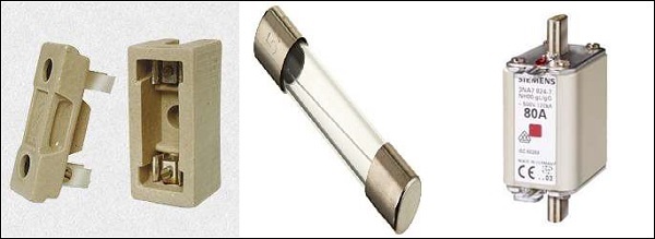
Fuse
Fuse is operated once in the circuit and then must be replaced after the trip occurs. It is helpful for phase by phase (single pole) protection. It offers a high breaking capacity at low volume, which limits electro-dynamic stress.
Following images show different types of fuse −
Circuit Breaker
Circuit breakers can be reset either manually or automatically. It automathy breaks the circuit within a short cutoff time and separates the load from the power supply that protects the circuit from any damage. The magnetic triggers of CB open the poles. CBs limit both the thermal and thermodynamic effects. It works faster than a fuse. For example, Molded Case Circuit Breaker (MCCB), Molded Case Switch (MCS), Air/Oil/SF6/Vacuum Circuit Breaker (ACB/OCB/SCB/VCB).
The following images show different types of circuit breakers:

Characteristics of Short Circuit Protection Devices
We will now learn the different characteristics of short circuit protection devices. The characteristics are shown below −
Breaking Capacity
The maximum value of the estimated short circuit current that can enable the device to break the circuit at a given voltage is called the breaking capacity.
Closing Capacity
The maximum short circuit current that can enable the device to reach its rated voltage at specific condition is called the closing capacity. It is the rational multiple of breaking capacity.
Electrical Safety - Earth Fault Protection
We will now understand what Earth Fault Protection is. We will being by focusing on Earth Fault.
Earth Fault
Earth Fault is an inadvertent fault between the live conductor and the earth. When earth fault occurs, the electrical system gets short-circuited and the short-circuited current flows through the system. The fault current returns through the earth or any electrical equipment, which damages the equipment. It also interrupts the continuity of the supply and may shock the user. To protect the equipment and for the safety of people, fault protection devices are used in the installation.
Earth Fault Protection Devices
The devices give the tripping command to break the circuit when earth fault occurs. The fault current is restricted and the fault is dispersed by the Restricted Earth Fault Protection (REFP) scheme. Normally earth fault relay, earth leakage circuit breaker and ground fault circuit interrupter, etc. are used to restrict the fault current.
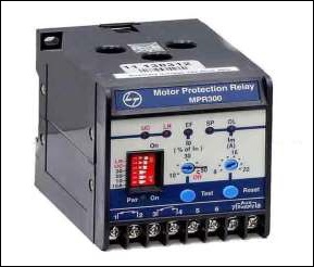
Earth Fault Relay (EFR)
It is a safety device used in electrical installations with high earth impedance. It detects small stray voltages on the metal enclosures of electrical equipment. The result is to interrupt the circuit if a dangerous voltage is detected. The EFR is protected against tripping from transients and prevents shock.
The following figure shows the Earth Fault Relay −
Earth Leakage Circuit Breaker
The Earth Leakage Circuit Breaker detects the leakage current directly and prevents injury to humans and animals due to electrical shock. It is a voltage-sensing device and has recently been replaced by Residual Current Circuit Breaker (RCCB), which is a current sensing device. It is a special type of latching relay that is connected to the main power supply. When the fault current flows from live wire to the earth wire within the installation, the coil of ELCB senses the voltage and switches off the power. This requires a manual reset process to work again. The RCCB senses the leakage current and sends a signal to trip the system.
Ground Fault Circuit Interrupter
The Ground Fault Circuit Interrupter is a safety device to prevent an electrical accident when any faulty tool is plugged in. It is a fast acting circuit breaker to shut down the supply when the earth fault occurs within 1/40th of a second. It compares the incoming and outgoing current from the equipment along the circuit conductor. If there is any difference as little as 5 mA, GFCI restricts the current and trip quickly. GFCI does not help much with line contact hazards but protects from fire, overheating and destruction of wire insulation.
Restricted Earth Fault Protection Scheme
Let us consider a star winding transformer, which is protected by a Restricted Earth Fault Protection with EFR protecting device as shown in the figure below.
The following image shows the Earth Fault Protection with EFR −

When an external fault F1 occurs in the network, I1 and I2 flow through the secondary side of the CTs. The resultant of I1 and I2 will be zero. However, if an internal fault F2 occurs inside the protective zone, only I2 flows and I1 is neglected. The resultant current I2 passes through the earth fault relay, which senses the fault current and protects the restricted portion of winding. The fault current is approximately 15% more than the rated winding current. To avoid the magnetizing inrush current, the stabilizing current must be in series with the relay.
Electrical Safety - Earthing
The process of transferring an unintended electrical energy directly to the earth through a low resistance wire is called electrical earthing. It refers to the connection of a noncurrent-carrying part of the equipment or neutral of supply system to the ground, which represents the zero potential. The leakage current chooses the simple low resistance path to flow. Thus, the electrical system and equipment are protected from damage.
Types of Electrical Earthing
The electrical equipment has two non-current carrying parts such as neutral of the system and frame of the equipment. Earthing system is also classified into two types.
Neutral Earthing
The process of connecting neutral of the system to the earth through a GI wire is known as Neutral earthing or System earthing. It is used in star winding systems including generator, transformer, etc.
Equipment Earthing
When the metallic frame of the equipment is connected to the earth by the help of a conducting wire then it is called Equipment earthing. In fault condition in the apparatus, the fault current flows to the earth and the system is protected.
Need of Earthing
Earthing is needed for the following reasons −
To protect the user from electrical shock.
Earthing system shows the easiest path to the fault current even after the insulation failure.
It protects the electrical apparatus used in the circuit from short circuit current, high voltage surges and lightning discharges.
Explanation
We will now understand the need of earthing considering the following conditions −
Normal Condition
Earthing of a system is done in the installation to connect the respective parts with electrical conductors or electrodes. The electrode is placed near the soil or below the ground level, which has flat iron riser under the ground. The noncurrent-carrying parts are connected with the flat iron.
The following figure shows the flow of fault current without earthing system −
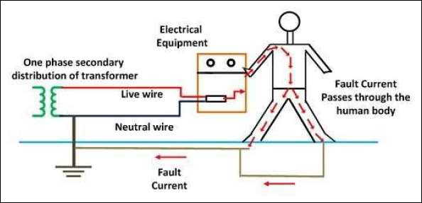
Fault Condition
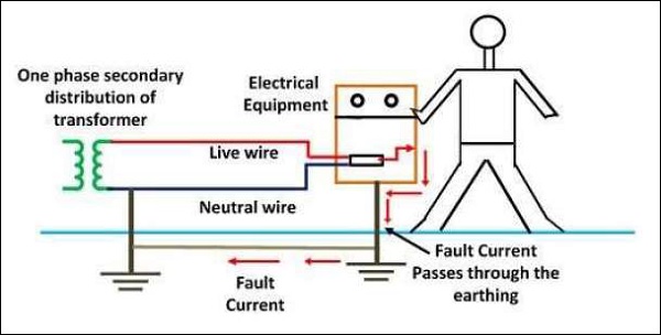
In a fault condition, the fault current flows from the equipment to the earth through the earthing system. Thus, the apparatus is protected from short circuit or fault current. At the fault time, the voltage of the electrode increases and equals to the resistance of the electrode and the ground fault.
The following figure shows the flow of fault current with an earthing system −
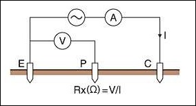
Ground Resistance Measurement
The ground resistance of an electrode is measured by the fall of potential method. The total set up is shows in the figure given below, where -
E is the earth electrode under test
P & C are two auxiliary electrodes placed at a suitable distance from E
I is the amount of current that passes between E and C
V is the measured voltage between E and P
The following figure shows the setup to measure ground resistance −
There is no appreciable effect on the resistance of E, if C is at an adequate distance from E. As the current into electrode P is very small, the electrode also has a negligible effect on resistance. Now varying the distance of electrode P from E, the resistance is measured.
The following figure shows the true resistance from the R vs d curve −
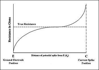
From the figure, the portion of the curve is marked as R of E, which is a nearly horizontal slope in the curve. The upward slope indicates the effect of the resistance of C. For the field measurement earth tester calibration, the ratio is directly used.
Risk reduction
The earthing system must follow the rules and regulations for the risk reduction according to the following standards.
Indian Standards: IS 3043- Code of practice for Earthing (latest)
National Electricity Code (NEC): 1985 of BIS
IEEE guide for safety in AC substation grounding No. ANSI/IEEE standard, 80-1986.
Proper inspection and field survey is necessary before the installation. A flowchart needs to be followed for the different steps: Inspection & Survey Design Testing Installation - Maintenance - Preparing Report.
Electrode resistance, soil resistivity is measured periodically and megger test should be exercised.
Do not use copper or aluminium wire as substitute, paint, enamel and grease on the electrode. Protect the electrode lead from mechanical stress and corrosion.
Proper training and management can reduce the risk factor.
Types of the Supply System
We will now learn the different types of the supply system. Before we begin, we need to know what power supply is.
Power Supply
The supply of electric power to an electrical load is called power supply. The main function of the power supply is to convert electric current from a source to the correct voltage, current and frequency to power the load. Electrical outlet, energy storage device such as batteries, fuel cells, generator, solar power converters are generally known as power sources.
Power supply is classified into different categories. In our subsequent sections, we will see what the different categories are.
DC Power Supply
Such type of supply supplies a constant DC voltage to the loads. It may deliver from a DC source or an AC source.
AC-DC Supply
AC energy can deliver DC power with the help of a rectifier, which converts the transformer output voltage to a varying DC voltage. The DC voltage passes through an electronic filter, which turns it into an unregulated DC voltage. There is also a register in series with the output to limit charging current and the final output power is fed to the load.
Switched Mode Power Supply (SMPS)
The main input is converted to DC voltage via rectifier and filter and then switched on and off at a high frequency (10 KHz- 1 MHz) by an electronic switch. It has a safety feature to protect the device and the user.
Linear Regulator
Linear regulator converts a varying DC voltage to a constant. There is a current limiting function to protect the power supply and load from overcurrent. It is independent of fluctuation in input voltage and loads impedance to provide a steady value.
AC Power Supply
AC power supply can be taken from the main supply transferred to the desired voltage with the help of step up and step down transformer. This supply is divided into a single-phase and a three-phase system.
Programmable Power Supply
A PPS provides remote control operation through an analog input or digital interface such as RS 232. The controlled properties include voltage, current and frequency (in case of AC).
Uninterruptible Power Supply
UPS has a feature to take power from two or more sources simultaneously. It is used as a backup supply as it takes over the load in dropout or failure condition of main supply. The process is so fast that the load never experiences an interruption.
High Voltage Power Supply
HDPS supplies the bulk of energy, which is hundreds or thousands of volts for applications above 20KV. It includes voltage multiplier or high turns ratio, high voltage transformer or both to produce a high voltage.
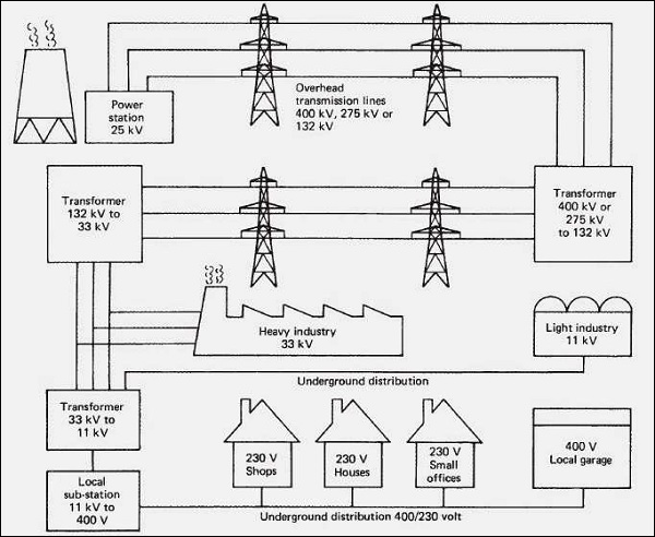
Principle of Power Supply
In modern power stations, the generation of electricity is at 25 KV and it is transformed to 400 KV. The number of generator sets are designed to provide the flexibility required power for seasonal variations in loads. The principle is to supply the power to any consumer with a ring system and fed from two directions carefully with proper protection and loss of supply.
The following image shows the distribution of power supply from power station to consumer −
Practice
A trained employee should be engaged in the practice of electrical works. Every electrical work must follow the following codes and standards including −
OSHAs electrical safety requirements for employee
National Electrical Codes
NFPA 70
Practice for external power supply is applicable for computer, electric vehicle, welding purpose, aircraft power supply and plug-in adapters.
Characteristics of Power Supply
The electrical characteristics of power supply refers to the quality of the power.
- Form factor
- Ripple Factor
- Rated Wattage
- Nominal Voltage
- Operating Voltage Range
- Input Frequency Range
- Efficiency
- Load Regulation
- Line Regulation
- Transient Response
- Hold-up Time
- Protections
- Peak Inrush Current
Questions
1. Which type of power supply needs an analog input?
a) High Voltage Power Supply
b) Programmable Power Supply
c) Switched Mode Power Supply
d) AC-DC Supply
Ans: b
2. Which of the followings are not required in AC-DC supply?
a) Transformer
b) Rectifier
c) Filter
d) Inductor
Ans: d
3. Which of the following is not characteristic of the power supply?
a) Trip time
b) Inrush current
c) Line regulation
d) Ripple factor
Ans: a
Electrical Safety - Cables
A cable is a group of wires swathed in sheathing that ensures a smooth electricity supply. It needs to be installed carefully following the National Electricity Code and National Building Code for various electrical applications.
Types of Cables
There are more than 20 different types of cables according to the design and application. Let us consider a few important types here −
Non-Metallic Sheathed Cable (NM Cable)
These cables have a flexible plastic jacket with two to four wires that are commonly used for indoor residential cabling and special varieties are for underground and outdoor cabling.
Underground Feeder Cable (UF Cable)
The wires in such cables are grouped together and embedded in the flexible material. These are useful for outdoor lighting and in-ground application.
Metallic Sheathed Cable (BX cable)
There are three stranded copper wires insulated with cross-linked Polyethylene and PVC sheathing. These cables are used for outdoor application and high-stress installation.
The following images show the different types of cables −
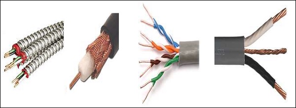
Multi-Conductor Cable (MC Cable)
More than one conductor that is insulated individually. The outer insulation gives extra security. The different varieties of MC cables are used in homes and music industries. For example, the audio multicore snake cable.
Coaxial Cable (Heliax cable)
A tubular insulating layer with a tubular conducting shield protects the inner conductor of the cable. As the two inner sheaths share the same geometrical axis, the name coaxial is justified. It is used for carrying television signals and connecting video equipment.
Unshielded Twisted Pair Cable (UTP)
UTP cable consists of two wires twisted together with solid copper cores and not insulated individually. These are often used in telephones, security cameras and data networks.
Ribbon Cable
It has various conducting wires running parallel to each other on a flat plane. Ribbon cables are applicable for low voltage applications such as in computers and its peripherals.
Direct Buried Cable (DB cable)
It either is a specially designed coaxial cable or bundled fiber optic cables, which have many layers of banded metal sheathing, heavy rubber coverings, and shock absorbing gel waterproof wrapped thread-fortified tape. This is considered a popular choice for transmission and communication requirements.
Twin Lead Cable (TL cable)
The TL cable consists of two wires that are generally used in the transmission of a signal from the antenna to receivers like TV and radio.
Paired Cable
There are two individually insulated conductors, which are used in DC or low frequency AC applications.
Twisted Pair Cable
The inner insulated wires in TPC are twisted or intertwined; otherwise, it is same as paired cable.
Importance of Thermal Resistance
Thermal resistance is the optimum temperature at which the insulation cable melts down. It depends upon the area of cabling the thermal phenomenon has taken into consideration when underground electricity network is designed. In an underground power system, the core temperature of cable should not exceed the maximum temperature of cable operation (65 C).
The following figure shows the variation of cable core temperature with increase in soil thermal conductivity −
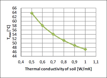
The thermal conductivity varies according to the material used in cable layer as the cable needs to dissipate heat to its surroundings.
| Cable Layer | Material | Thermal Conductivity () |
|---|---|---|
| Conductor | Copper | 400.00 |
| Insulation | XLPE | 0.3232 |
The thermal conductivity of soil changes the intensity of heat transfer from the power cable. As the conductivity increases, the soil receives heat faster and the cable temperature lowers down. The soil conductivity depends upon the water content (caused by rainfalls or droughts) and moisture. The distribution of temperature should be done effectively while working in the underground electrical network system.
Safety precautions
Let us now consider a few safety precautions −
Do a safety plan, which includes emergency activities, evacuations suitable to the codes and standards.
Professional and trained electricians should be employed, who understand the safety protocols and surrounding workplace environment.
Workers must use non-conducting gloves, safety eyewear, shoes and protective clothing to protect from electrical risks.
Maintenance and testing should be done periodically.
Questions
1. Which material is used to cross-link the core in Metallic Sheathed Cable?
a) Copper
b) PVC
c) Polyethylene
d) Aluminum
Ans: c
2. Which cable is suitable for cameras and data networks?
a) Twin Lead Cable
b) Unshielded Twisted Pair Cable
c) Direct Buried Cable
d) Twisted Pair Cable
Ans: b
3. What happens to the cable core temperature with increase in soil thermal conductivity?
a) Increases
b) Decreases
c) No Change
d) Cant be predicted
Ans: b
Classification of Hazard-Prone Areas
The electrical apparatus may produce heat, arc and spark during normal and abnormal condition. This increases the risk of fire and explosion in the presence of flammable, combustible, ignitable gases, vapors, liquids, dust or fibres. A few locations have also been considered hazardous. As per NFPA 497 and NEC Article 500 and 501, the hazardous areas are classified into different categories. Let us learn about the different categories in our subsequent sections −
Class I Location
This location contains flammable gases, vapours or liquids, which create fire or explosion hazards. The practice for the classification of class I hazardous NFPA 497 (reference 2) provides locations.
Division 1
The ignitable concentrations of flammable gases, flammable liquid produced vapors or combustible liquid produced vapors exist in this location under normal operating conditions.
Division 2
The ignitable concentrations of flammable gases, flammable liquid produced vapors or combustible liquid produced vapors exist in this location under abnormal operating conditions.
Group Designation
There are four groups based on their physical properties −
- Group A − Acetylene
- Group B − Hydrogen
- Group C − Carbon Monoxide
- Group D − Gasoline
Class II Location
The fire or explosion hazards exist due to combustible dust in Class II location. NFPA 499 specifies electrical/electronic equipment for safe and proper installation in Class II location.
Division 1
The combustible dust is present in the air under a normal operating condition, which is sufficient to produce explosive mixtures. These are moderate to dense dust cloud, which form dust layer greater than 3.0mm.
Division 2
The combustible dust is present in the air under an abnormal operating condition, which is sufficient to produce an explosive mixture. These are not visible dust cloud, which form dust layer less than 3.0mm.
Group Designation
The combustible dust is grouped into three types based on their physical properties.
- Group E − Titanium
- Group F − Carbon Black
- Group G − Nylon Polymer
Class III Location
The fire or explosion hazards exist due to ignitable fibres in this location.
After the classification of hazardous area, the explosive atmospheres are divided into zones based on the frequency and persistence of the potentially explosive atmosphere.
For gas, vapor and mist -
Zone 0
This explosive atmosphere consists of a mixture with air of dangerous substances in the form of gas, vapor or mist continuously or for long periods or at intervals.
Zone 1
A mixture with air of dangerous substances in the form of gas, vapor or mist is present occasionally in normal operation in this categorized atmosphere.
Zone 2
The mixture of dangerous substances is present in the form of gas, vapor or mist and persists for a short period only.
For dust -
Zone 20
This atmosphere consists of explosive materials in the form of a cloud of combustible dust in the air continuously, or for long periods or at intervals.
Zone 21
There is explosive combustible dust in the form of a cloud in the air in normal operation occasionally.
Zone 22
Explosive combustible dust is present in the form of a cloud in the air and persists for a short period.
Characteristics of hazard-prone areas
Let us now see the characteristics of hazard-prone areas. The characteristics are as follows −
Properties of dangerous substances
It includes the boiling point and flash point of any flammable liquid, gas or vapors, which may be lighter or heavier than air.
Size of potential release
This is the consequence of wrong circumstances where rapid rescue is dangerous. For example, LPG cylinder or cartridge.
Temperature and pressure
When some substances do not form explosion without any heat and pressure.
Ventilation
Proper ventilation can prevent the fire and explosion.
Choice of electrical apparatus for use
The equipment is constructed as per the standards to be prevented from being a source of ignition. These are categorized as 1, 2 and 3 depending on the level of the zone according to the suitability of application. The mechanical equipment is not certified for use in the hazardous area. If the categorized equipment is not available, then lower category can be used combining with other protective measures.
Category 1 − Zone 0 & Zone 1 or Zone 2
Category 2 − Zone 1 or zone 2
Category 3 − Only Zone 2
Questions
1. Which flammable materials exist in location III?
a) Ignitable fibres or flyings
b) combustible dust
c) flammable liquid
d) All of the above
Ans: a
The place where combustible dust in the form of a cloud in the air is present in normal operation is known as______.
a) Zone 0
b) Zone 21
c) Zone 2
d) Zone 22
Ans: b
3. Which one is not characteristics of the explosive atmosphere are?
a) Size of potential release −
b) Ventilation −
c) Population
d) Temperature and pressure −
Ans: c
Measures Related to Gas/Ducts/Fibre material
It is very important to consider safety measures while working with gas, ducts, fibre material. It is recommended that a person working with these should wear the required safety attire and carry all the necessary tools.
Safety measures related to gas
The incident rate has reached 6% because of electrical cases in oil and gas companies all over the world. Safety precautions play a vital role and help in avoiding electrical hazards.
For reliability and safety reasons, checking periodically and keeping electrical system in good condition is necessary after the installation.
Proper care and experience are needed for the expansion, modification, revamping of existing facilities when working with a live plant.
Need to be professional to choose perfect electrical equipment for installing in a gas industry. For example, HRC fuse is suitable for such industries instead of a kit-kat fuse.
Electrical equipment installation, design, testing and maintenance must follow the standards of respective nationalities to ensure the expected quality as well as the safety.
Safety measures related to duct/ fibres
The duct or conduits are the pathway of cables and protect them.
The electrical conduits must follow the standard specifications of -
- ASTM F2160
- NEMA TC7
- UL 651A & B and UL 2024
- National Electrical Code (Chapter-9)
It is essential to focus on the diameter of conduit ∓ inner duct, number of inner duct, length & direction, the composition of the duct, the coefficient of friction, jam combination, pull speed, temperature, elevation, inner duct weight, mechanical stress, tension and bending radii, etc.
Trained professionals must choose the ducts as per the requirement of the environment including underwater, underground, outdoor location or indoor location. Use symbols for the underground cabling that can restrict the people from digging and facing accidents.
Electrician must use tension meter, cable lubricants and required electrical equipment.
Safety measures related to fibre material
Fibre optic cables need to be handled with care with proper knowledge about bending radius, and cable twisting.
Use laser beam to find damages in the optical communication cable.
Do not stick the broken ends or drop fibre pieces on the floor. Avoid skin contact with the fibre material.
Remember not to drink or eat anything near installation area.
Group classification of flammable gas/ vapor
A flammable gas or vapor can be ignited from an arc or spark at the electrical system and results in dangerous accidents. There are four Class I group classifications in section 500-5(a) as per NEC.
Group A: Acetylene
Group B: Hydrogen and gases equivalent to hazardous in nature
Group C: Ethyl Ether or gases or vapors which are equivalent to hazardous nature
Group D: Gasoline, alcohol, acetone, natural gas & similar material
These groups were made as per the level of hazard related to the explosion pressures of the specific atmosphere. Besides these engineers should follow Practice for the classification of flammable liquids, gases or vapours in NFPA 497.
Group classification of Duct
There are different types of electrical ducts or conduits used for various applications.
Galvanized Rigid Conduit
The thickness of galvanized steel tube protects the electrical wiring and become the choice of an electrician in commercial and industrial applications.
Electrical Metallic Tubing
Such conduits are made of steel or aluminum and restricted to a specific radius for bending. It is very popular in commercial, residential and industrial buildings.
Electrical Nonmetallic Tubing
It is moisture resistant and flame retardant and it is easy to bend by hand due to the flexibility.
Flexible Metallic Conduit
It is known as Greenfield of flex means it doesnt maintain permanent bend. It is recommended for dry areas.
Liquid-tight Flexible Metal Conduit
These are covered by a plastic waterproof coating which is applicable for general wiring in wet or damp locations.
Rigid Metallic Conduit
It is made up of coated stainless steel or aluminum which prevents corrosion.
Liquid-tight Flexible Non-metallic Conduit
These are the flame resistant type which is recommended as a raceway for installation of approved conductors (Rating- 600 volts).
Aluminum Conduit
It is used in large amounts of water areas and corrosion prone areas as it prevents corrosion.
PVC Conduit
It resists moisture and corrosion, which has also the higher thermal coefficient of expansion.
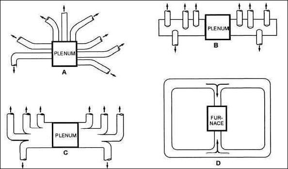
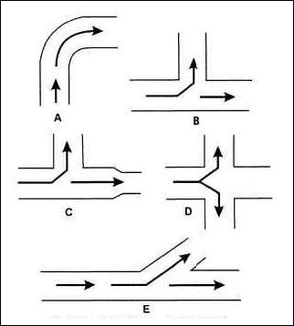
Based on the design and shape electrical ducts are classified as follows −
- Individual Round Pipe
- Extended Plenum
- Reducing Trunk
- Multiple Return Air
The following figure shows the different supply duct systems −
The following figure shows a typical duct connection and has
- Elbow
- Tee
- Reducing Tee
- Cross
- Lateral
Questions
1. Class I group classification of flammable gas/ vapor/liquid is described in ______.
a) NFPA 70
b) NEC Article 500
c) IS
d) None of these
Ans: b
2. Which group does flammable gas Hydrogen belong to?
a) Group D
b) Group C
c) Group B
d) Group A
Ans: c
3. Which one of the followings is known as Greenfield Flex?
a) Liquid-tight Flexible Metal Conduit
b) Galvanized Rigid Conduit
c) PVC Conduit
d) Flexible Metallic Conduit
Ans: d
Classification of Temperature
We will now learn about the classification of temperature. In addition, we will also understand the importance of temperature.
Importance of Temperature
Temperature is one of the most essential factors in process engineering to detect a hazardous condition in plant and in equipment. The Safety Integral Level (SIL) measures the safety instrument function. SIL specifies a target level of risk reduction. The International Electro-technical Commission (IEC) 615081 standard assigns SIL to the devices, which are able to eliminate device fault and detect the fault.
Classification of Temperature for Electrical Equipment
There are some insulation classes, which allow a maximum permissible temperature for the safety of devices. Electric instruments can be downsized by insulation technique of higher thermal endurance.
The following table shows maximum allowable temperature and the materials used for various types of insulation −
| Insulation Classes | Maximum Permissible Temperature (C) | Material Used |
|---|---|---|
| Y | 90 | Cotton, silk or paper |
| A | 105 | Reinforced Class-Y materials with impregnated varnish or insulation oil |
| E | 120 | Combination of different materials |
| B | 130 | Inorganic material with adhesives |
| F | 155 | Class-B materials that are upgraded with adhesives, silicon and alkyd-resin varnish of higher thermal endurance |
| H | 180 | Inorganic material glued with silicon resin or adhesives of equivalent performance |
| C | >180 | 100% inorganic material |
Classification of Temperature for Hazardous Areas
The temperature classification describes the threshold temperature for the hazardous area. The value of minimum ignition temperature is classified from T1 to T6. This classification of temperature identifies a temperature that an instrument will produce at ambient environment temperature (40 C). The identified temperature is called maximum surface temperature.
T1 − The minimum ignition temperature > 450 C and the maximum surface temperature generated by the instrument is 450 C.
T6 − The minimum ignition temperature > 85 C and the maximum surface temperature generated by the instrument is 85 C.
| Temperature Classification | Minimum Ignition Temperature | Temperature Maximum Surface Temperature |
|---|---|---|
| T1 | >450C [842F] | 450C [842F] |
| T2 | >300C [572F] | 300C [572F] |
| T3 | >200C [392F] | 200C [392F] |
| T4 | >135C [275F] | 135C [275F] |
| T5 | >100C [212F] | 100C [212F] |
| T6 | >85C [185F] | 85C [185F] |
If there is any measure issue that occurs with the hazardous area instrument, it can be repaired. The repair section is of three basic categories.
Factory Repair Only
The device must go through some safety test procedures and returned to the factory.
Field Repair
It is difficult to instruct the end user technician practically. If there is any difficulty to solve the issue, an authorized factory personnel should be employed.
Field Repair by End-user − This involves direct replacement in terms of form, fit and function.
Temperature Measurement
Temperature measuring instrument is designed in accordance with the safety standards. In industrial environment temperature measurement is required for a wide variety of needs and applications. A large number of sensors and devices fulfill such demand. The measuring instruments are as follows −
- Thermometer
- Thermostat
- Thermistor
- Thermopile
- RTD (Resistance Temperature Detector)
- Thermocouple
Questions
1. In which insulation class the inorganic material with adhesive is used?
a) Class E
b) Class Y
c) Class B
d) Class A
Ans: c
Explanation − According to table 1, the inorganic material with adhesive can permit only 130C insulation which refers to Class B type.
2. What is the maximum surface temperature (in C) in the T4 type of temperature?
a) 100
b) 135
c) 200
d) 235
Ans: b
Explanation − According to table 2, the lower hazardous is a classification of temperature is T4 which allows 135C of maximum surface temperature to cause a hazard.
3. Which of the following is not a temperature measuring instrument?
a) Thermocouple
b) RTD
c) Thermistor
d) Barometer
Ans: d
Explanation − Thermocouple, RTD and thermistor are the temperatures measuring instrument but barometer measures air pressure.
Protection Against Weather Complexities
It has now become common that with bad weather like storm or heavy rains, there will be loss of power or electricity. This affects the masses at large. And, people at the coastal regions are the most affected when there is failure of electricity due to flooding. 67% of the electrical outage instances have been a result of natural calamities such as lightening, snowfall and wind. To minimize the cost and mitigate issues of outage, protecting electrical assets is necessary.
Protecting Electrical Network
In this section, we will see how to protect electrical networks from natural calamities.
Maintenance
For critical systems, UPS and the backup generator should be installed and maintained properly. If the power is cut off from the grid, the backups are utilized. Regular maintenance service ensures the reliability of equipment and safer work environment.
Electrical Network Design
Correct electrical design minimizes the voltage transients generated when there is lightening. An electrical model should be tested through all possible scenario; the faults and weaknesses of various areas are to be predicted. A proper design should provide −
- redundancy
- alternative paths
- automatic transferring loads
Testing of System
The backup supplies and alternative paths should be tested periodically. Consider testing the following −
the condition of backup equipment
the system logic in case of failure or for new installations
the response of site personnel in emergency situation when the utility supply fails
Management
Data management and analytics help in predicting the problems, finding solution to prevent the problems or solve an already occurred problem. The management system focuses on the following two areas −
Outage Management System
The OMS provides data and information from a variety of sources, faults, allowing maintenance and engaging electrical workers to repair and restore.
Asset Management System
A track record of facilitys assets, predicted lifecycle and technical specifications must be maintained to ensure a reliable and resilient network.
Protection against extreme weather condition
The extreme weather condition refers to the lightning that could be catastrophic for the electric devices. Consider the following points to keep your devices safe.
An electrical surge can fry a circuit board of electronic equipment like TV, laptop and sound system, etc. A top-notch surge protector can be used to prevent the damages.
There are three characteristic that need to be considered while buying a high-quality surge protector (SP) −
Low clamp level − It takes a voltage to trigger the SP and to divert the electricity to the ground
Low response time − It takes nanoseconds of time to respond the surge
High surge capability − It takes some amount of voltage that an SP can take and function properly
It is not required to depend upon the warranty of SP. Attach a status check light with it which shows the last surge.
Avoid overloading a power strip surge protector, which may increase the risk of damaging the electronic equipment.
Standards against Dirt and Water
According to the International Electro-technical Commission (IEC) standards 60529, the International Protection Marking classifies the degree of protection which is provided against intrusion, dust, accidental contact and water by the mechanical casing and electrical enclosure. The Ingress Protection (IP) defines from which the equipment is protected in normal condition. The first digit indicates the protection of equipment against solids. The second digit indicates the protection of equipment against harmful entry of various forms of moisture.
The following table lists down the IP Codes and their meanings −
| 1st digit | Protection from Solid | 2nd digit | Protection from Moisture |
|---|---|---|---|
| 1 | Hand Protected: protection from solid objects greater than 50mm in diameter | 1 | Drip proof against vertical water drops |
| 2 | Finger protected: protection against the object > 12.5mm | 2 | Drip proof when tilted at angles up to 15 |
| 3 | Tool protected: protection from the object with a diameter or thickness > 2.5mm | 3 | Rain/Spray proof when water falling at an angle up to 60 |
| 4 | Wire protected: protection against the objects with a diameter or thickness > 1.0mm | 4 | Splash-proof when water splashed from any direction |
| 5 | Dust accumulation protected: protection from the dust interfering with the operation | 5 | Jet proof when water projected through a nozzle(dia 6.3 mm) at a pressure from any direction |
| 6 | Dust penetration protected: protection against penetration of dust | 6 | Jet proof when water projected through a nozzle(dia 12.5 mm) at a pressure from any direction |
| 7 | Watertight proof when temporary immersion in water | ||
| 8 | Pressure watertight when continuous submersion in water |
The following table lists down the letters that define hazardous parts. Some other letters provide additional information related to the protection of the equipment.
| Level | Hazardous parts |
|---|---|
| A | Back of hand |
| B | Finger |
| C | Tool |
| D | Wire |
The following table lists down a few letters in IP codes −
| Letter | Meaning |
|---|---|
| F | Oil resistant |
| H | High voltage device |
| M | Device moving during water test |
| S | Device standing still during water test |
| W | Weather conditions |
Questions
1. Which device requires nanoseconds of time to respond the surge?
a) Low clamp level device
b) Low response time device
c) High surge capability device
d) None of these
Ans: b
Explanation
Justifying the name, the low response time device requires only nanoseconds of time to respond to the surge, recognize the fault and commands the protective device to trip.
2. IP codes follow the standard of __________.
a) IEC
b) BIS
c) NFPA
d) NEMA
Ans: a
Explanation
The International Electro-technical Commission of Europe describes the Ingress Protection of mechanical and electrical enclosures of equipment.
3. What is the meaning of enclosure IP56?
a) Protection against insertion of the finger and vertically dripping in water
b) Dust resistant and can be immersed in water
c) Protection against dust and high-pressure water jets from any direction
d) None of these
Ans: c
Explanation
In IP56, the first digit 5 refers to protection against dust and the second digit 6 refers to the protection from high-pressure water jets from any direction. By combining both digits, the outcome refers to option C.
Safe Electrical Equipment Design Characteristics
We will now learn the design characteristics of safe electrical equipment. Let us being by understanding what is examination of equipment.
Examination of Equipment
It is important to examine electrical equipment, which may cause serious physical hazards. It ensures that the equipment is free from recognized hazards. Consider the following important points for the safety of equipment.
Suitability of equipment is identified according to the labeling and specification
Mechanical strength and durability
Electrical insulation
Heating effect under the condition of the area
Arcing effect
Practical safeguarding of employees
Use of Electrical Equipment
The electrical equipment should be installed in accordance with the given instructions including the type, size, voltage, current capacity and specific use. The devices must indicate the purpose only after it is reviewed and the arrangement has been made for it to fulfill the purpose. Even a small device has its own importance. For example, disconnection of a switch enables a circuit to be opened and stops the flow of electricity. The equipment must withstand weather, chemicals, heat, corrosion or any hazardous environment.
Working with Electrical Equipment
It is very important for a person working with electrical equipment to be qualified to work on the equipment. Working on live parts always creates hazards without using the personal protective equipment. Clean the cutting material on the floor after the work. There must be a storage room to keep the equipment safely. The workspace must be wide and well ventilated. An electrician must follow the standards of NEC, NBC, NFPA, and IEC, etc.
Safety Requirement for Electrical Equipment
Verification and testing will guarantee the safety and quality of the equipment. Confirmation of equipment in accordance with the product standards is the prime importance of an installation. The grounding of equipment is necessary to divert the fault current, which will be permanent and continuous. High temperature may lose the continuity of ground-fault path. So Ground Fault Circuit Interrupter must be used to prevent injury from electrical wiring. It would provide an extra protection to the device. The breaking of insulation of cable occurs simply by aging. This may lead to shocks, burns and fire. So periodic maintenance of electrical equipment is required. The maintenance predicts and prevents the damage. The equipment needs to be protected from lightning by installing the surge protection system.
The best process of protection is automatic disconnection of supply which can be provided by the implementation of system earthing. An electrician should have sufficient knowledge about the standardized system (TT, TN and IT system). Protection against overload, short circuits and earth leakage current can also protect the device from damage. Each item must be well insulated and packaged.
Standards for Designing Electrical Equipment
There are some internal standards that need to be followed while designing the electrical equipment. The standards are as follows −
International Electro-technical Commission (Europe)
Institute of Petroleum (UK)
International Standards Organization (worldwide)
British Standards Institution (UK)
American Petroleum Institute (USA)
Engineering Equipment and Materials Users Association (UK)
Electricity Council (UK)
Institute of Electronic and Electrical Engineering (USA)
Questions
1. Which of the following is not a fact for the safety of equipment?
a) Mechanical strength and durability
b) Electrical insulation
c) Color of equipment
d) Heating effect under the condition of the area
Ans: c
Explanation
To examine the safety equipment, mechanical strength, durability, electrical insulation and heating effect under the condition of the area are a few points that need to be considered. However, it does not depend on the color of the equipment.
2. Which device prevents injury from electrical wiring?
a) MCB
b) ACB
c) Switch
d) GFCI
Ans: d
Explanation
The Ground Fault Circuit Interrupter senses the fault and temporarily breaks down the circuit within few milliseconds. This prevents injury from electrical wiring.
3. Which organizations standard does every manufacturer follow to design electrical equipment?
a) IEC
b) ISO
c) IEEE
d) All of the above
Ans: d
Explanation
A manufacturer must focus on the specification, type, safety, testing, application and quality of equipment. Therefore, the manufacturer must choose the standards of International Electro-technical Commission (IEC), International Standards Organization (ISO) and Institute of Electronic and Electrical Engineering (IEEE) to design electrical equipment.
Electrical Safety - Test Certifications
We will now understand what electrical safety test certifications are. Let us begin with the concept of Electrical Product Certification.
Electrical Product Certification
A product must pass the performance test, quality assurance test and meet the specifications for certification scheme. The certification scheme includes
Federal Communications Commission (FCC)
Telecommunication Certification Body (TCB) program
Environmental Protection Agency Energy Star Program
International Commission on the Rules for the Approval of Electrical Equipment Product Safety Certification Body Scheme
Material Analytical Services Certified Green IEQ program
Worldwide Accreditation Bodies
All recognized bodies are listed for accreditation to the ISO 65 standard by the International Accreditation Forum (IAF). The recognized bodies are −
American National Standards Institute (ANSI)
Accreditation Board (a sub-division of ANSI)
American Association for Laboratory Accreditation (A2LA)
International Accreditation Service (IAS)
United Accreditation Foundation (UAF)
Technischer berwachungsverein (TV)- Germany
Korean Accreditation Board (KAB)- Korea
Safe Electrical Work Certification
The regulatory system promotes safety satisfying the standards. The work should be controlled and enforced through the certification system. Therefore, certification is required for such work. The Energy Provision Act 2006 defines two different classes of electrical works Controlled work and Restricted work. The scope of both the works has been established by the Commission for Energy Regulation.
Controlled Electrical Work
There are some electrical works, which need experienced people to work for safety reasons. Controlled work comes under the scope of the regulatory system at outset. A Registered Electrical Contractor must do the certified controlled works or an inspector from the Safety Supervisory Bodies may also do the work. The certificate describes the confirmation that the electrical work has been tested properly. Safety verification with national standards according to the national wiring rules is an important category of certification. The work must be significant enough in the context of electrical safety and needs to be controlled through the issuance of a completion certificate. The likelihood for like replacements of switches, sockets, lightning fitting to an existing circuit must be done as per the compliance with the Technical Rules. Such works define the Scope of Controlled Works. This involves installation, commissioning, inspection and testing work as defined in Part 7 of the National Wiring Rules ET101 and ET105. The inspection of the electrical installations must confirm the Regulation 89 of Sl. No. 732 of 2007.
Restricted Electrical work
The current scope of restricted works was decided in 2013. It involves the electrical installation in any locations listed in part 7 of National Rules for Electrical Installations. The inspection, testing or certification of existing Electrical Installations is described in Chapter 62 of the National Rules for Electrical Installation. This work is only applicable to domestic environments.
Testing of Equipment
In this section, we will learn about the testing of equipment undertaken by different recognized organizations −
CPRI
The Central Power Research Institute tests the electrical equipment such as transformer, reactor, switchgear, cable, duct, capacitor, arrestors relay, insulator and renewable energy products and thereby, generates a test report.
BSI
The BSI provides Certification Board (CB) report for the apparatus of IT equipment, control & wiring accessories, electronic component, medical equipment, cables, and environment.
ERDA
The Electrical Research and Development Association shows the excellence in testing, calibration, R & D with the support of Council of Scientific and Industrial Research (CSIR) for different products such as cables, transformer oil, energy meter, switchgear, T & D lines, lamps & luminaries, dielectrics, polymers and photovoltaic cell.
ITC
The ITC Pvt Ltd. provides testing services for ingress protection, LED products, battery, PV module, cable gland and domestic appliances, etc.
NRTL
The Nationally Recognized Testing Laboratory is a private organization under OSHA and ensures OSHA electrical safety standards. It authorizes the manufacturer to apply the registered certification for a particular product.
The testing service of any organization must follow several IEC standards such as −
| Sr.No. | Standards & Testing Equipment |
|---|---|
| 1 | IEC 61010-1 Lab Instruments |
| 2 | IEC 60204-1 Control Panel |
| 3 | IEC 60595 LED Luminary |
| 4 | IEC 61347 Lamp control gear |
| 5 | IEC 60950 Information technology equipment |
| 6 | IEC 60601 Electro-medical equipment |
| 7 | IEC 60065 Audio video & similar product |
| 8 | IEC 61439 Low voltage switchgear & control gear assemblies |
| 9 | IEC 60034 Rotating electrical machine |
Questions
1. Who can include any organization as accreditation body in worldwide?
a) IAF
b) ANSI
c) KAB
d) UAF
Ans: a
Explanation
All recognized bodies are listed for accreditation to the ISO 65 standard by International Accreditation Forum (IAF).
2. What is name of the laboratory recognized by OSHA?
a) CPRI
b) ERDA
c) NRTL
d) None of these
Ans: c
Explanation
Nationally Recognized Testing Laboratory is a private organization under OSHA and ensures OSHA electrical safety standards.
3. What is the standard code of testing LED luminaries?
a) IEC 60065
b) IEC 60595
c) IEC 60601
d) IEC 60034
Ans: b
Explanation
Any organization must follow LED luminaries testing services according to the International Electro-technical Commission 60595 standards.
Procedure to Mark Unprotected Equipment
We will now learn about the procedure to mark unprotected equipment. To begin with, we will look into the industry safety practices.
Industry Safety Practices
Let us now look into the safety practices in the electrical industry.
Intended use
Select the device according to the purpose and use within the specified limit. Do not use the external auxiliary device
Instruction and safety
Contact the technical assistant to ensure how to use the device according to the safety labels and tags.
Installation
Refer Material Safety Data Sheet (MSDS) and understand the processing characteristics of the material. Ground the equipment and install protective devices.
Operation
Use safety devices like guards, interlocks, and protect yourself with Personal Protective Equipment. Ensure that you see the signs of potential in a proper manner.
Maintenance & repair
Do a scheduled maintenance at intervals and confirm the correct operation of the device. If any fault occurs, replace it or repair it.
Equipment safety information
The specific conditions that an equipment can withstand are mentioned in the manual for the equipment or on the equipment. We also need to abide by a few precautions while handling and working with the electrical equipment.
Avoid open flame in the site area
Check the pressure daily to protect the equipment from wear, damage or leaks
Do not point dispensing handgun at anyone
Do not remove the molten hot melt cable with bare skin
If you encounter a disaster, seek medical attention immediately
Shut down the equipment safely as the level of shut down varies from one device to another.
General safety warning and caution
Every equipment comes with warning and caution symbols provided by the manufacturer. It is important that an electrician understand the warnings and symbols and handles the equipment accordingly.
The following table shows a few safety label and their description −
| Sr.No. | Safety Label | Description |
|---|---|---|
| 1 |  |
Warning − Risk of electrical shock. It may cause injury or equipment damage if not observed correctly. |
| 2 |  |
Warning − Potential hazardous situation. It can cause serious injury including death. |
| 3 |  |
Caution − Potential hazardous situation. It can cause minor or moderate personal injury. |
It is recommended to carefully understand the type of equipment. It is also important to know the placement of equipment and what is to be kept away from it.
HM - Hot Melt Caution: To stay away from the hot surface. If hot metal gets in contact with a hot surface, then it might lead to a disaster.
PC - Process Control - Warning: Untrained or inexperienced personnel may lead to equipment damage and personal injuries.
CA - Cold Adhesive - Warning: Do not use high pressure. It may release cold adhesive causing personal injury.
Approved symbols present on devices
The following table lists down a few approved symbols present on devices
| Sr.No. | Icons | Meaning |
|---|---|---|
| 1 |  |
Corrosive product |
| 2 |  |
Product hazardous to health |
| 3 |  |
Toxic product |
| 4 |  |
Product harmful to the environment |
| 5 |  |
Explosive product |
| 6 |  |
Product meets European safety requirements |
| 7 |  |
Restriction of certain hazardous substances in electrical/electronic equipment |
| 8 |  |
Safety Extra Low Voltage |
Marking at Site
In this section, we will the different marks on a site and understand what they mean.
Barricading and signage
There are different types of barricades use at the location. The following table shows a few barricades −
| Type | Description | Example |
|---|---|---|
| Caution | Access permitted but caution required. It highlights hazardous area. |  |
| Danger | Access permitted under the instruction of authority. Restricted area: hot work, falling object, unprotected edge. |  |
| Dont Enter/ Electrical Work | Used for switchboard, distribution line maintenance. |  |
| Radiation | Access permitted under the instruction of Radiation safety officer. |  |
| Incident scene | No access for any unauthorized person if an incident has occurred. |  |
| Barrier mesh/ Bunting flag | It is used to highlight the boundary of the work area. |  |
| Solid Barricade | This signage means establishing a safe distance from plant or equipment |  |
Questions
1. What is required to understand about the equipment at the time of installation?
a) barricade
b) Symbols
c) MSDS
d) None of these
Ans: c
Explanation
Material Safety Data Sheet (MSDS) is referred before the installation of an equipment.
2. Which barricade is/are required to highlight the boundary of work area?
a) Barrier mesh
b) Radiation
c) Bunting flag
d) Both A & C
Ans: d
Explanation
According to the safety standards, Barrier mesh and Bunting flag are used to highlight the boundary of work location.
3. Which symbol represents the product that is harmful to the environment?
a.
b.
c.
d.
Ans: b
Explanation
Each symbol defines a product such as A represents hazardous to health, B represents harmful to the environment, C represents corrosive material and D represents explosive material.
Maintenance of Unprotected Equipment
We will now understand the maintenance of unprotected equipment. Here, we will also delve into the different types of maintenance.
Types of Maintenance
The technical actions regulate the normal operation of equipment that is divided into two major groups −
- Preventive
- Corrective
Preventive/ Predictive Maintenance
Preventive maintenance does not mean to maintain the equipment at the time of malfunctioning but to prevent the failures before it arises. It is applicable to prevent the breakdown. This type of maintenance is performed over a period of time, then it is called as Scheduled Maintenance that reduces the risk of malfunction and degradation of equipment. Preventive maintenance focuses on equipments type that manages to adopt predictive and conditional maintenance.
The predictive maintenance defines the equipment status through utilization of various non-destructive testing and measuring techniques. The predictive preventive maintenance program ensures efficient, reliable and safe production.
Corrective Maintenance
When any fault, failure or malfunction is detected, corrective maintenance is applied to the equipment. As the name suggests, it is useful in order to correct the issues. It cannot be pre-determined like preventive maintenance. It focuses on the infrastructure of equipment. It is referred as emergency maintenance. Such maintenance must be carried out efficiently in the equipment.
Preventive Checks
A routine preventive maintenance needs checking to prevent damages in electrical equipment. Consider the checklists given below to follow preventive checks −
Cleaning Machines
Clean the machine at regular intervals and apply oil to the unprotected metal surface.
Lube the Machine
A good lubrication can keep safe the turret, spindle, dry gears, bearings and oil reservoir and protect from wear and corrosion.
Skim oil off the machine
Oil skimmer is used on the surface of the machine to create a perfect breeding ground and removes dermatitis, dry skin, nasty smells and poor tool life.
Monitor machine-cutting fluid
A refractometer monitors the water-based fluid concentration weekly. Another kit checks the PH level. The backlash and alignment should be checked quarterly.
Repairs
If there is any issue with the maintenance, the equipment requires repairs for smooth functioning. The art of repair facility is responsible to repair and modify all types of electrical equipment parts. There are certain parts of devices that need to be checked frequently and repaired accordingly.
Transformer
Repairing of leaks, bushings, housings, radiator fins, gaskets and indicators is done and damages can be replaced. Transformer oil will be replaced if the air level is degraded.
Circuit breaker
Obsolete parts should be supplied otherwise, circuit breaker can be replaced. A trained professional should diagnose and ensure the fault.
Switchgear
If there is any tear, accident or electrical fault found in switchgear and control gear by experienced engineers, then repair facility repair the broken parts or replace the equipment.
Protective relay
During troubleshooting, engineer should check if the operation of relay meets the specifications or not. If something wrong is reported, then it is repaired, recalibrated or replaced.
Cables
A Cable is an equipment in the electrical system. A single fault in the cable can shut down the whole system. The splicing is checked and the cable is replaced immediately.
Statutory Audit
In case of maintenance, the repairing and replacement process requires some financial support and generation of reports. Thus, statutory audit pitches in. It is to define a fair view of the financial statements such as balance sheet, income and expenditure account, receipt and payment. It shows the distribution of fund regarding electrical material repairing, purchase, etc.
Scope of SA
According to the financial management system, the scope includes −
Adequacy of project financial system: Effectiveness of accounting, financing, operation control, compliance with plans, policies, procedures, the reliability of accounting system, data and reports and verifying assets and liabilities.
All documents, records and accounts must be kept carefully for a project.
Questions
1. Which maintenance is applicable after a fault occurs?
a) Preventive maintenance
b) Corrective maintenance
c) Both A & B
d) None of these
Ans: b
Explanation
When any fault, failure or malfunction is detected, corrective maintenance is applied to the equipment.
2. If preventive maintenance is offered monthly, then it is called ______.
a) Corrective maintenance
b) Emergency maintenance
c) Scheduled maintenance
d) Protective maintenance
Ans: c
Explanation
When preventive maintenance is performed over a period of time, then it is called Scheduled Maintenance.
3. Which device measures the concentration of fluid?
a) Barometer
b) Thermistor
c) Refractometer
d) None of these
Ans: c
Explanation
- Barometer measures air pressure.
- Thermistor measures temperature.
- Refractometer measures the concentration of the fluid.
Electrical Safety - Duties and Obligations
We will now learn the duties and obligations of various stakeholders related to the use of electrical equipment.
Supplier Obligations
The relationship between a supplier and a customer is a contractual relationship. However, the supplier must abide by a few moral duties to ensure customer satisfaction.
Reliability
The functions of a product should meet the consumers expectation.
Service life
The consumers mind has calculated the life of a device. Therefore, the product needs to perform efficiently during the expected time.
Maintainability
The product must be repaired or replaced during or after a specific duration.
Product Safety
It is a degree of risk related to the product that the product must be safe in normal condition.
Replacement
If a product does not meet the expected specification or if it is a faulty item, provisions for its replacement should be made.
Specification
The type, nature, components of product and the hazards related to the product must be specified clearly.
Technical Assistant
A technical assistant should visit the location to repair, maintain and provide a good after sales service.
Documents
The terms and conditions document including invoice, guarantee, warranty certificates, test reports and installation guide must be provided.
Moral Duties of Manufacturer
Consider the following points related to the moral duties of a manufacturer −
Duty must comply with the claims of reliability, service life, maintainability and safety
Duty of disclosure
Not to misrepresent and coerce
Due-care Theory
It is a known fact that a manufacturer enjoys an advantageous position than a consumer. So, it is the responsibility of the manufacturer to take special care of the consumer's trust and interest. This theory is known as the due-care theory. According to this theory, a supplier is responsible in the following areas;
- Design
- Production
- Information
Commercial Advertising
Advertisement plays a vital role to establish relations between producers and customers. The perks of advertising are −
- It attracts the audience
- Creates the intention to buy in a customer
- Creates the desire for the product
- Leads the customer to buy the product
Duties and obligations of a plant owner
Let us now see the duties and obligations of a plant owner. A plant owner needs to look into the following −
Project Management
The project of a plant commission goes through the following steps −
Mechanical work completion − Installation of piping, equipment, integrity, inspection, cold alignment, point-to-point continuity checks and preservation
Pre-commissioning − Cleaning, testing, air and steam blowing, flushing, passivation, system energizing and instrument verification
Commissioning − Operational testing, loading, running the equipment, electrical function testing, and safety testing
Acceptance of test run − A small unit operates for 12 hours continuously
Human Resource Management − After all the paper works and successful commissioning, the owner has a responsibility towards its employee. Managing engineers, technicians and operators is necessary for a successful start-up.
Plant Operation
A successful plant commission consists of four parts out of which if one fails, the plant would not be considered a successful one.
No lost time accidents − The safety factor bothers every beginner. So, there is more stress on design, construction and commission.
No equipment damage − This function is all about discipline in each section of the design, construction, operation and commissioning team.
On test product: The testing team should take a reasonable period to complete the testing of the product.
Less than two days − Very good
Seven days − Acceptable
Above fourteen days − Less than Acceptable
No environment incident − The successful making of a test product within a specific period defines this function and ensures no environmental hazards.
Healthy and Safety Environment
As the other plans include the inherent risk, a Health Safety and Environment Management Plan should be planned properly for the project. Therefore, the following procedures should be followed for each location of work.
- Identification of system
- Pre Start-up Safety Reviews (PSSR)
- Permission to Work System
- Identification of Hazards and Risk Management
- Simultaneous Operations (SIMOPS)
Questions
1. What is the acceptable duration for testing a product?
a) More than seven days
b) Less than seven days
c) More than fourteen days
d) Less than fourteen days
Ans: b
Explanation
The testing engineer should specify the time taken for the product testing.
- Less than two days is considered very good
- Seven days is acceptable
- Above fourteen days is less than acceptable
2. Which section the Due-care theory does not emphasize on?
a) Testing
b) Design
c) Production
d) Information
Ans: a
Explanation
According to the Due-care theory, a supplier has the responsibility in the areas of Design, Production, and Information.
3. Which one of the following is not a component of the HSE management system?
a) Identification of system
b) Pre Start-up Safety Reviews (PSSR)
c) Pre-commissioning to work system
d) Permission to Work System
Ans: c
Explanation
The components of Health Safety and Environment Management System are
- Identification of system
- Pre Start-up Safety Reviews (PSSR)
- Permission to Work System
- Identification of Hazards and Risk Management and Simultaneous Operations (SIMOPS)
Electrical Safety - Primary Ex-protection
The hazards are generally created in chemical factories, refineries, and paint workshops, cleaning equipment, mills and stores for milled products and in tank facilities and loading areas for flammable gases, liquids and solids. The explosion protection defines the health and safety at the workplace.
The principle of Explosive protection
When a mixture occurs in air under an atmospheric condition with flammable substances in the form of gas, vapor, dust, fibers or flyings, explosion hits the workspace. Safety parameter is a function of the pressure, temperature and oxygen. So the limitations are necessary. There are three factors of the explosion.
- flammable material
- Oxygen (Air)
- Source of Ignition
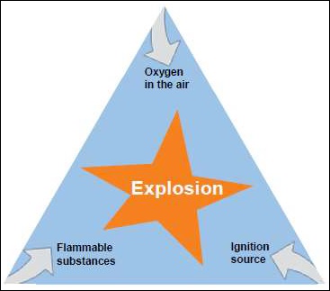
Figure 1: Basis of Explosion
By limiting any one of the above factors can reduce the probability of primary explosion and protection can be determined accordingly.
Basic/Primary Ex- protection
Primary explosive protection is a process to reduce the number of flammable substances or atmospheric oxygen to a point which ensures no danger of explosion. The open layout and proper ventilation increases air circulation and flushes the air. It is not possible to completely replace the atmospheric oxygen of an area where people work. According to the analyzing facts there are three possibilities of an explosion in presence of flammable gas.
Due to heat − open flame/hot surface/hot gases
Electrical Sparks − opening and closing of contacts, short circuit, static discharge
Mechanical Spark − friction, hammering, grinding
The first question arises that is there any form of dangerous materials which potentially causes an explosion. Then what is the quantity of those combustible substances? The potential of an atmosphere for explosion needs to be measured. The primary ex-protection implementation and compliance should meet ex-protection rules and standards.
Primary Ex-protection Measures
The main aim of primary ex-protection is to prevent the formation of dangerous substances. The protection measures are only to reduce the probability of occurrence of such materials and its spreading capacity. The measures must be cost-effective. Some of the protection measures are below −
Try to use incombustible or less volatile substances or replace critical components if possible.
System parts should be used with inert gases such as nitrogen.
Dilute the combustible liquids with a non-reacting material such as water.
Reduce the number of combustible substances.
Moistening of dust is necessary.
Regular cleaning also reduces the number of dust.
Use enclosures filled with inert substances
Provide natural or artificial ventilation systems which limit the concentration of flammable materials.
Install dangerous gas detection system which can provide a notification through an alarm or breaking of the system.
The flash point of flammable liquid should be changed by adding other materials such as water. Otherwise the processing temperature must be lowered. If the flash point of a flammable liquid is above the processing temperature then the faults, stand-stills, leakage come under control.
Questions
1. Which one is not a factor of explosion?
A. Oxygen
B. Electrical spark
C. Acetylene
D. None of these
Ans: D
Explanation − No fire exists without oxygen in the air. An electrical spark is a source of ignition and acetylene is a flammable substance. So A, B and C are the factors of the explosion.
2. Why is ventilation necessary for every workplace?
A. To flush the air
B. To circulate the air
C. To limit the concentration of flammable substances
D. All of the above
Ans: D
Explanation − All (A, B, C) are related to each other which are the works of a ventilator. Ventilation is necessary for a workplace for circulating and flushing the air that reduces the concentration of combustible substances.
3. Which substances are used in the enclosures?
A. Water
B. Inert gases
C. Alkali materials
D. All of the above
Ans: B
Explanation − The inert gases dont react with any material. So enclosures are protected by inert gases.
Electrical Safety - Secondary Ex-Protection
If electrical equipment has been kept under protection against explosion, then it does not necessarily mean that it would be a totally sealed or encapsulated unit.
Types of Protection Techniques
There are seven known types of protection techniques. Let us take a look at the different techniques −
Type M or Type h (Hermetically sealed)
This is a design where the equipment is kept under a complete sealed environment. The parts that can possibly ignite gas or vapour by being exposed to atmosphere are hermetically sealed with resin. It is suitable for Zone 0, 1 and 2 areas. Usually, small compressors, miniature motors and small lamps get this kind of protection scheme.
Type q (Sand Filled or Powder filled)
Here, an enclosure is filled with quartz sand of 1.6mm size having weight of 0.1% of water. The electrical equipment is placed inside of it. When any arc generates inside because of any ignition, it gets absorbed by the sand itself. It is mainly used for Fuse banks and Capacitors. It is suitable for Zone 1 and 2.
Type O (Oil Immersion)
It is similar to type q with very little difference; here sand is replaced by mineral oil. The enclosure shows high and low oil level on its body. It is used for circuit breakers, transformers and switching units. Zone 2 areas go through similar safety procedure.
Type P (Pressurized Apparatus)
In this case, the enclosure gets pressurized with a gas that is more in value than the atmosphere pressure. By so, the equipment present inside remains safe from outside gas and vapour. The process is called purged gas technique. It is used for Zone 1 and 2 areas.
Type I (Intrinsically Safe)
Unlike the above ones, it is not an enclosure; rather, it is a circuitry design. The concept is to limit the current and voltage input within the ignition energy required to ignite the inflammable gases/vapours or air mixtures under normal or anticipated fault condition. It is used for Zone 0, 1 and 2 areas.
Type e (Increased Safety Design)
This safety scheme is solely for Zone 2 areas. Here, the enclosure designed is usually of cast metal or Mould Polypropylene or fabricated sheet metal. The size of the enclosure is decided in such a way that the surface temperature can be limited within the planned temperature class.
Type d (Flameproof or Explosion proof design)
It is a very popular technique. Zone 1 areas usually go through such safety scheme. Here, the equipment to be protected is kept inside a cast metal of CI or LM-6 type. Sometimes, a moulded reinforced polypropylene GRP enclosure is also used. Precautions are taken to avoid the occurrence of explosions. Even if it occurs, it will get extinguished by moving inside.
Precautions Against Highly Flammable Contents
In an industry, the presence of highly inflammable materials, increase the risk of hazard to its container (structure) and to the persons working close to it. The events can turn more dangerous if the structure gets hit by a lightening stroke. That is the reason; for such areas, a higher degree of safety and protection scheme needs to be followed.
If a structure contains highly flammable solid, liquids or gas vapours then consider the following recommendations −
Use all-metal structure for storage of flammable materials
Keep flammable liquid or gas inside an all-metal structure. In case the degree of hazard is high, it is better to go for a gas-tight structure.
Close any openings in the structure
Sometimes, due to lack of inspection, a small opening in the gas or vapour chamber leads to trouble. It directs the lightening flames to enter inside thereby causing explosion. So, it is highly recommended to seal those openings.
Regular maintenance of containers
It is the duty of the safety inspector to put the containers for daily/weekly checks. A keen follow-up will make the flaws public beforehand and the safety officer can take appropriate step to avoid the possible dangerous consequences.
Avoid the accumulation of flammable air-vapour mixtures about such structures
Lightning flames can charge the flammable air-vapour particles easily and can travel through them to their source. In this regard, it is important to keep the air-vapour mixture of these structures away from the contact of lightning by any mean.
Reduce the spark gaps between the metallic conductors
Inside the structure, there may be some conductors having space between them. In due course of time, the accumulation of flammable air or vapours inside those gaps can create hazardous situation on being exposed to lightning. When lightning strikes, the flammable air or vapours turn into charged particles and may possibly cause sparks between the conductors. Thus, on a regular safety check, it is required to reduce the spark gaps.
Location of the structure
Some locations are prone to lightning and if the structure is present in such areas, then it is likely to get hit by lightning every now and then. Here, the primary duty is to move the structure from that place to another place, more immune to lightning strike, almost immediately. Otherwise, it will lead to catastrophic hazards not only to the instruments present inside but also to the personnel working near to that.
Create multiple zones of protection
This is in line to the point that we discussed just before. If the structure is not in a condition of getting transferred from the position of a high prone lightning area, then it is important to create multiple zones of protection around the structure. The lightning has to go through a number of protection layers before reaching the structure.
Safety Measures During Handling Lighting Protection Equipment
For buildings containing highly flammable liquid or gas, it is important to guard them from lightning. However, handling lightning protection equipment is not a childs play. A single mistake can cause serious hazards to the structure and the persons working near to it. Depending on the type of building to which the lightening protection equipment have been integrated, there are different handling methodologies. Let us understand what the methodologies are.
Building with explosive dust or flammable vapour risk
For such type of building, it is recommended to add an integrally mounted lightening protection system. It should have vertical air terminals and horizontal air terminals. Depending on the type of storage inside the building the height of the vertical terminals must be set at minimum 1.5 metre whereas the horizontal air terminals must be spaced 3 to 7.5 metre from each other.
Explosive storage building and explosive workshops
Here, it is required to add integrally mounted systems. The vertical and horizontal spacing in this case should be 0.3m high and 7.5m spaced respectively.
Small explosive storage buildings
Buildings of such type are very less to get hit by lightning. The integral mounted systems are not necessary over here. Only a vertical pole type lightning protection scheme can work wonders.
Storage of explosives in buildings
There are some buildings that contain explosives such as Nitroglycerine (NG). These structures need suspended horizontal air terminations as integrally mounted systems and vertical pole types will not be able to provide the desired protection. These suspended horizontal air terminations should be placed at a minimum height of 2m above the structure. About the internal spacing, it should be minimum 3m between the terminations.
Electrical Safety - Bonding
A fault current always seeks for the low resistance path and through that travels to the nearby systems thereby damaging them to the core. In this regard, all major members of metallic structure should be bonded and well connected as per the lightning protection system. This includes the continuous metal reinforcement and services of the concerned metallic structure.
Such bonding should be made at least at two places around the structure. They should be equally spaced and the gap between them should not exceed 15m. The structures contain metalwork frames. The metalwork frames should also be bonded to the lightning protection system.
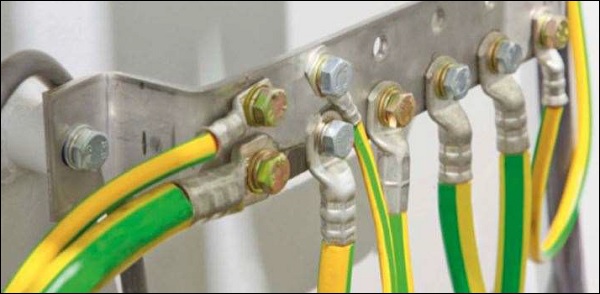
All the conductors entering inside should be metal-cased. The metal casing should be electrically continuous within the structure. It is the critical responsibility of the safety officer to inspect the structure.
The point at which the conductor is marking its entry inside the structure should be earthed with respect to the supply side and should be bonded directly to the lightning protection system.
There is a different bonding strategy concerned to the conductors of the structure connected directly to the overhead lines. Here, a buried cable of metallic sheath of armour should be connected between the overhead line and the point of entry to the structure.
Surge protective devices like voltage-dependent resistors can also be connected. The earth terminal of this protective device should bond with the cable sheath or armouring. Bonding of such type will keep the overall structure safe from lightning.
Electrical Safety - Transformer Safety
Transformers are a major source of power supply to any industry.
The conversion of voltage level can cause serious damage to a person or to the nearby area if not kept under tight protection measures. It is the duty of safety inspector to run the following condition assessments on the transformer with the following checklist −
Main transformer inspection check list
| Task | Yes | No | N/A | Comments |
| Main Tank | ||||
| Paint System in Good condition | ||||
| Rust Observed | ||||
| Tank grounds in Good condition | ||||
| Conduits and fittings secure | ||||
| External core ground provider | ||||
| Oil Leakage observed | ||||
| Cooling system | ||||
| Radiator or cooler fins cleaned | ||||
| All valves to main tank open and secure | ||||
| All fins in place and operational | ||||
| All oil pumps in place and operational | ||||
| Oil flow indicators function properly | ||||
| Excessive vibration or noise observed | ||||
| Leaking of oil if any | ||||
| Oil Preservation | ||||
| Positive pressure of inert gas | ||||
| Proper setting of regulator of Nitrogen blanket | ||||
| Correct pressure check of gas blanket | ||||
| Bushing | ||||
| All clean and zero defect | ||||
| Proper check of oil levels | ||||
| Oil leakage if any | ||||
| De-energized tap changer (DETC) | ||||
| Location of Position indicator tap | ||||
| Locking mechanism checked | ||||
| Load Tap Changer (LTC) | ||||
| Location of Position indicator tap | ||||
| Silica gel breather | ||||
| Oil leakage if any | ||||
| Control Cabinet | ||||
| Connections/components in good condition | ||||
| Weather tight seals checked | ||||
| Strip heaters checked | ||||
| Protective devices | ||||
| Oil Temp indicator reading | ||||
| Oil Temp indicator set points | ||||
| Winding Temp indicator reading | ||||
| Winding Temp indicator set points | ||||
| Buchholtz relay alarm/trip | ||||
| Gas detector alarm/trip |
Electrical Safety - Motor Handling Safety
Majority of unintentional injuries today are caused by motor accidents. Equipment users in a high-energy environment suffer from severe hazards, when no effective precautions are adhered to. Given the multitude of the risks involved, it is important for users to apply and follow safety practices. There are various factors that lead to such accidents - alcohol influence, inexperienced drivers, absence of seatbelts or the disturbance caused by toddlers. These factors need to be addressed separately. Averting motor injuries would mean taking safety measures for different types of vehicles.
Safety for single phase motors
Single-phase motors include all those devices the output power of which is approximately 1 Horse Power (1HP). A single-phase motor is widely used for domestic applications such as washing machines, electric toys, fans, blowers among other devices. In order to ensure the safety of these devices, it is important to take the following precautions −
Constant troubleshooting to establish whether the features in the single face motors devices are working properly.
Conduct a proper inspection of the motor winding.
Perform a power supply test to determine whether there is any problem by the motor.
Do not leave a short-circuited battery for long because it would eventually explode.
Do not power the motors beyond 12 volts.
Safety for 2 phase motors
Before you start working on 2-phase motors, ensure you observe all the basic guidelines for safety. The lack of adhering to safety precautions often result in injuries like shock, fire or personal injuries. Some of the safety precautions include the following −
Persons not having the knowledge of operation should not be allowed to the working areas where 2-phase motors are operating.
Always remember to wear goggles to ensure safety of your eyes.
Never leave a motor to operate unattended.
Safety for 3 phase motors
Three-phase motors comprise of heavy industrial machines. The machines require high voltage to operate them, hence extreme measures ought to be taken to prevent accidental injuries that may be hazardous in nature. Before you operate on these machines, ensure you wear safety gears such as gloves, boots and ear masks to safeguard yourself against harmful effects.
Taking safety measures while operating motors is an important aspect since it ensures the safety of the person working on it. Therefore, extreme care has to be taken by the safety officer. Motor users should wear all necessary safety equipment required for preventing any fault. Adhering to these measures helps in detecting abnormalities.
Electrical Safety - Generator Handling Safety
Standby generators are required to combat power outages. These are convenient and easy to use but can be hazardous to life and property. It is important to follow proper standards, procedures and adequate precautions during installation, operation and maintenance of the power generators. It is recommended to create a safe working environment by consulting the manufacturer, reading manuals and following guidelines. Safety practices not only ward off hazards but also increase quality and service life of the equipment.
Safety Precautions during Installation and Maintenance
The safety of generators depends on several sections starting from the selection to maintenance. Any mistake might lead to a serious hazard.
Selection of a Generator
The selection depends on the number of apparatus that need to be energized in case of power failure. According to the demanded constant wattage and surge rating, the generator is selected.
Installation Process
Authorized, qualified and certified technicians and engineers who have the knowledge of generators, safety codes and standards must be employed. The installation process must satisfy NFPA 110 information on Standards for Emergency and Standby Power System.
Operation
In operational condition, the generator exhausts fumes (poisonous gas like Carbon monoxide) need to be ventilated properly. The area should be free from any combustible material.
Maintenance
Regular inspection and periodic maintenance of generator parts, cables connection and batteries are required. The air intake system, fuel system, exhaust system, electrical systems and control system need to be checked within a schedule. If any damage is detected, replace it immediately.
Inspection of Generator for Safety
Routine inspection can reduce the occurrence of hazards. For diesel generators, the exhaust, fuel, engine and DC electrical system are required to be monitored closely.
Lubrication Service − The oil level and quality must be checked using a dipstick at regular intervals.
Cooling System − The level of coolant is checked. The radiator is cleaned without damaging the fins.
Fuel System − Up store the fuel before it degrades. Testing and polishing are also major requirements. The air cooler pipe and hoses should be checked for leaks, holes, cracks, dirt and debris.
Testing Batteries − Battery testing and cleaning are necessary to deliver adequate starting power. The terminals are washed with the solution of baking soda and water and coated with petroleum jelly. The specific gravity and level of electrolyte are checked. If the hydrometer reads below 1.215 then charge the battery. If the electrolyte level is low, then fill the filler neck with distilled water.
Engine Exercise − The engine exercise should be done at least once in a month for 30 minutes from loading to a no-load condition. The engine should be clean all the time.
Exhaust System − All the connection points, welds and gaskets are recommended to be checked properly for any leaks and should be repaired immediately.
Questions
1. Which standards must be followed for the installation of the generator?
a) NFPA 70
b) NFPA 85
c) NFPA 110
d) NFPA 100
Ans: c
Explanation
NFPA 110 describes the Standards for emergency and standby power system, which includes the installation process of the generator.
2. Which gas is exhausted by the generator in running condition?
a) Nitrogen
b) Oxygen
c) Carbon monoxide
d) All of the above
Ans: c
Explanation
In operational condition, the generator exhausts poisonous gas like Carbon Monoxide.
3. At which point of electrolyte specific gravity, the battery needs to recharge?
a) less than 1.215
b) more than 1.215
c) equal to 1.215
d) None of these
Ans: a
Explanation
The battery is required to charge again, when the specific gravity of electrolyte is less than 1.215. This is measured by a hydrometer.
Electrical Safety - Crane Handling Safety
The loads can be raised, lowered or moved with the help of the crane and its foundations. It is a risky task for an operator. If there is any type of failure such as structural failure, overturning, collapse, loose contacts or falling objects, it can harm the load, other equipment and workers. To eliminate the hazards the OSHA standards describes the procedure for safe load handling with cranes. It also covers the equipment safety and the responsibilities of a crane operator for safe crane operation. Before handling the load, the crane system is required to check minutely.
Pre-Use Safety Checking
It is always recommended to go for precautions to ward off hazards. The inspection ensures crane safety by testing it vividly.
The workspace should be a wide area and a registered crane is used to handle the material.
The operator should be well qualified, certified and licensed to use cranes.
The workplace factors like ground bearing capacity, wet or windy climate are considered for the safety of crane.
The installation and commissioning activities must be supervised by an expert.
The components must be assembled in the correct sequence including a limit switch, load indicator, sling connection, ropes, and other attachments.
If there is any defective system present then replace it immediately.
Check the crane for oil leakage, vibration or sound.
Be familiar with the control device.
Check the indicators such as load indicator, workspace limiter, anti-collision device and crane motion indicator.
Check the hook block and make sure that it is good in working condition
Check the wire rope for any deformation like a broken wire, strand distortion, kinks, excessive wear, bird caging, crushing, rusty and stretching.
Make sure that the sling angle is always greater than 45
Operational Safety
The operator must consider the following safety problems and avoid accidents while working with crane and hoist.
| Sr.No. | Description | Examples |
|---|---|---|
| 1 | There are no new hazards on the operating environment. | 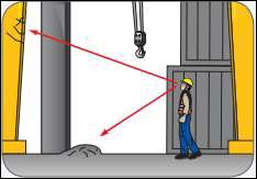 |
| 2 | Assumptions and doubts lead to accidents. | 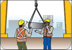 |
| 3 | Crane must take the load from the center not from the side. Avoid swinging of the load | 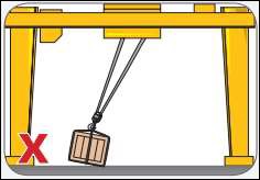 |
| 4 | Dont lift the load over people | 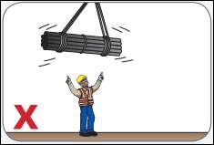 |
| 5 | Dont pull the hoist rope or chain as a sling |  |
| 6 | Dont try to be a multi-tasker | 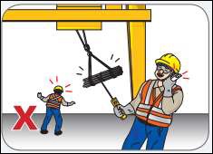 |
| 7 | Ensure the load is connected properly and communicate clearly with other team members | 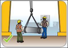 |
| 8 | Ensure the clearance between cranes and fixed objects. A 750mm and B 600mm | 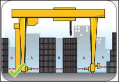 |
| 9 | Dont leave suspended load unattended | 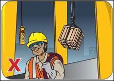 |
Emergency Safety
The emergency plans should be prepared at the time of installation for each workplace where the crane will operate.
There should be an emergency entry and exit facility from a crane.
The emergency plan should be tested for its effective response and the same must be notified to the emergency services.
The emergency procedure training must be provided to the workers.
Medical facility should be available near the operating area.
The evacuation location signs should place at a point where the workers can see everything at the workplace.
Questions
1. How much is the sling angle for safety purpose?
a) less than 45
b) more than 45
c) less than 60
d) more than 60
Ans: b
Explanation
If the sling angle is greater than 45, then the load will be lifted properly parallel to the horizontal surface. If the angle differs, then the load will be tilted and may cause hazards.
2. How much is the safety clearance between the crane and load?
a) 750mm
b) 750mm
c) = 750mm
d) None of these
Ans: a
Explanation
For safety purpose, the calculated clearance between crane and load is more than 750mm.
3. What will happen when the crane lifts the load from a side?
a) the load will be tilted
b) load swings
c) the load may fall down
d) All of the above
Ans: d
Explanation
If the crane lifts a load from one side, then the load will tilt, swing or fall down. This can lead to hazards. So it is recommended to lift the load at its centre.
Measures During Preventive Maintenance
If the plant and its accessories are not inspected and maintained regularly, they eventually become unsafe for workers working with or around them. Machines may breakdown causing loss of business. Therefore, to curb such mishaps, a periodic maintenance coupled with safety check is essential. Now, gaining the knowledge on periodic maintenance is not sufficient, it is also important to know the safety measures that one should follow while carrying out preventive maintenance at the site.
Safety Measures for Preventive Maintenance
Let us now see the different safety measures for preventive maintenance.
Wear accessories
No safety inspection and maintenance should be carried out without any protective equipment. For example, gloves, masks, eye guards, boots, jackets, etc.
Circulate work permit
If you are going to do an offline maintenance of a crane, issue a work permit and circulate the message amongst the workers beforehand. Otherwise, due to lack of knowledge, the person working on the equipment may encounter a risk.
Conduct risk assessment
Before proceeding with the maintenance activities, a risk assessment must be done and all workers must be involved in this one. It will help workers to gain better understanding about the process and will enable them to conduct their own additional assessment of the risks involved.
Effective and continuous communication
Most of the times, it is the half-broken information chain that causes mishaps during preventive maintenance. As discussed earlier, every employee of the company should be informed about the going-to-be preventive maintenance at least 3 days in advance. In addition, the safety officer must consider letting the workers inform about the same on the day of maintenance as well.
Consider the tools
Preventive maintenance is subjected to test a machine to its maximum capacity. Therefore, it should not be compromised just because you fall short of the right tool. Collect the necessary tools, wires, testers and other equipment required to run the test without exposing yourself to high voltage and current.
Always have someone to watch your back
It is always a good practice to carry out the preventive maintenance work in a group of two or three. When you work as an individual, the risk factor goes up. However, when you have someone to watch your back, the risk factor tends to be low.
Electrical Safety - Types of Safety Equipment
The chances of occurrences of hazards at the work place cannot be ignored. So, each employee should be provided with adequate personal protective equipment (PPE) as per Section 19 of the Constitutional Safety and Health Act 1984.
Categories of Personal Protective Equipment
Personal Protective Equipment can be considered in the following different categories.
Respiratory safety
Chemicals, dust can enter inside the body through breathing thereby causing chest pain, headache and other symptoms related to breathing problems. Therefore, respiratory safety equipment like disposable filtering half mask, half mask, full face mask, etc. are necessary.
Eye Safety
Following equipment are used to protect the eyes −
- Safety glasses
- Eye shields
- Goggles
- Face shields, etc.
Ear safety
Hearing protection equipment are necessary to protect the eardrums if the noise or sound level exceeds 85 decibels. For the protection, equipment like earplugs, semi-insert ear plugs and ear muffs can be used.
Hand safety
Harmful substances and chemicals can get absorbed into the skin thereby causing bruises, cuts, abrasion, etc. To avoid these, hand safety equipment can be used such as gloves, finger guards and arm coverings.
Foot Safety
In plant areas, falling from height, rolling down, crushing or penetrating pointed material are more common. To protect the foot from all these, employees need the following −
- Safety toe shoe
- Metatarsal guards
- Toe guards
- Leggings
- Studded treads, etc.
Head Safety
Protecting employees from potential head injuries forms the major part of any safety program. Therefore, employees are provided hardhats. The hardhats are divided into three categories
- Class A (Vol res up to 2.2k volt)
- Class B (Vol res up to 20k volt)
- Class C (provide protection against light weights)
Implications of Human Behaviour
The role of a human in the workplace is of great importance. No matter how technologically equipped, an organization gets, it will always require a human for operating and monitoring. The safety of a worker lies in his/her approach towards a machine. Careless attitude while running a machine results in accidents and even death in some cases. It is quite significant to analyze a workers behavior towards the machine so that you can stop any electrical hazards in future.
Identification of Accident
In this section, we will see how to identify an accident. The following points need to be considered to identify an accident −
Cause of Accident
Identifying the reason that leads to the accident.
Events
A detailed analysis of the chain of events, that leads to the accident.
Difference between accidents
Comparing the current accident with previous accidents.
The intensity of risk
Identifying the risk involved in the task that is being carried out by the workers.
Organizations fault
Find out if it is the workers fault or the organizations.
Improving the System
In this section, we will learn how to improve the system.
Task Analysis
Each work requires a different set of actions and each action of a worker has a ripple effect on the other. Each task carried out by a worker needs some degree of choice by the worker and that choice sometimes can cause hazards in the workplace.
Follow the example given below to have a fair idea about task analysis.
Example
Suppose a worker at a workplace is asked to raise the temperature of the Air Conditioner by 2 degrees. Now, this task seems easy to execute, but errors can occur due to human behavior. Consider the following actions that can cause errors −
Pressing the wrong button
A slip type Error will happen if the worker does not know which button to press and presses the wrong button assuming it the right.
Execute without knowledge
The worker pushes the right button, but during that time he/she thought (guessed of his/her own) that the switch is for other use.
Violation
In this situation, the employee is perfectly aware of which button to press but still presses a wrong button to complete the task sooner.
Choice Analysis
All humans tend to make mistakes at workplace especially during the end of their shift, as they are tired and focus on reaching their home as soon as possible. Therefore, while evaluating the human behaviour and performance, one must consider the fact that no human is 100% perfect. When a worker faces stress inside or outside the work, he/she is most likely to commit a mistake. Addressing the issues can help to prevent the errors and avoid any accidents in future.
The Choice analysis of a worker is categorized into two perspectives −
Personal perspective of the worker
- Age
- Gender
- Personal characteristics
- The way of learning
- The tendency to take a risk
Workplace perspective of the worker
- Organizational culture
- Office politics
- Reward System of the organization
- Management system
- Quality of training provided by the organization
Classifying Human Errors
In this section, we will classify the different human errors.
There are two types of classification approach −
- PHECA − Potential Human Error Cause Analysis
- SHERPA − Systematic Human Error Reduction and Prediction Approach
PHECA
Potential Human Error Cause Analysis focuses on the tasks given in workplace and the error he/she commits. Tasks could be about an operation, maintenance, monitor, check, and communication.
Following are the errors caused by workers −
- Task not done
- Partially completed the task
- Done the task but not precisely what was asked for
- Done the task more than what asked for
- Done the task before the specified time
SHERPA
Systematic Human Error Reduction and Prediction Approach combines the task and the error methods. The approach stores the error type separately. SHERPA tie the errors of a worker to his/her performance goal. The causes of the error are linked to the workers skill or the knowledge he/she possess.
Questions
1. Identification of accident in an organization is crucial. Which one is not a method of identifying a workplace accident?
a) Cause of an accident
b) Events leading to an accident
c) Number of people involves in the accident
Ans - c
2. Which one of this does not fall under personal perspective of a worker while conducting choice analysis?
a) Personal Characteristics
b) Reward System
c) The tendency to take a risk
Ans - b
3. What does PHECA Stand for?
a) Potential Human Error Cause Analysis
b) Potential Human Error Cause Awareness
c) Personal Human Error Cause Awareness
Ans - a
Do's and Don'ts at a Glance
Confusing a live equipment for a dead one is one of the major reasons that can result in an electrical accident. It is essential for an organization to train their workers properly to take appropriate precautions while operating machinery. Although, it is also the responsibility of a worker to work with extreme caution and abstain from hazardous situations as much as possible.
The do's for a worker
In this section, we will learn about the actions that need to be performed by a worker.
Before carrying out any task, make sure that the equipment is 100% dead and is in no condition to get energized at any stage of work.
For proper caution, it is ideal to write down all the measures that you are going to take, on a control sheet.
Reanalysis your written instructions, and if possible, you can discuss this with your supervisor or fellow workers.
Always stick with the work instruction provided to you.
Using a well-rated instrument is necessary. It is recommended that only good quality, insulated tools, probes, and prods are used.
Working in the sequence is the key to a safe operation especially the switching sequences. Make sure you close the isolator first and then close the associated circuit breaker.
While testing equipment, it is vital that you create a spacious exclusion area.
While working in the field, it is your life that is at stake. So, you must take appropriate cautions while working. Before taking any risk, it is always recommended that you think of the repercussion and take adequate measures.
If you found anyone is interfering with your way of work, then stop them politely. If a co-worker is working on your test area and following a wrong procedure, then insist him/her to follow the right method.
Before starting your work, make sure that you draft a proper layout of all your equipment in proper order. Following a correct order will not only help you to provide a comfortable working position but also offer you other advantages such as −
Provide ample of space to work
Provide ease of accessibility to your equipment
Allows you appropriate time and visibility to read your instructions
Provide adequate light
Provide you quick gateway during an emergency
The don'ts for a worker
In this section, we will see the different actions that should be avoided by a worker.
Never try to reclose a circuit during a fault, when it is still under process. A fault should always be located and then it should either be removed or rectified. Until proper steps have been followed, do not do anything with the circuit.
Unless the motor load has been disconnected, do not try to open the supply of the alternator set.
If the primary winding is capable of allowing current flow through it, then never try to open-circuit the secondary winding. Also never, use the secondary winding open-circuit as an energizer for primary winding.
Before working on a circuit make sure, it is entirely dead or has been discarded by an authorized worker. Until then, it is better to maintain your distance from it.
While using test equipment, never try to interact with any safety devices as it is quite unsafe.
While running a zdc machine, it is crucial to make sure you arrange an armature and open the field circuit at the same time. Without proper provisions, do not ever attempt to run a DC machine. However, you can try it with caution only if you secure the circuit breaker in the field circuit.
While using test equipment never alter, any permanent connects and even if you do, make sure you consult correctly with your supervisor. If you modify test equipment, make sure you label it with block letter. After using the equipment, replace the connection to its original position unless your supervisor has asked you not to do it.
Never use damage equipment or leave faulty equipment at a place that is accessible by others.
Even if your injuries seem light, always get yourself adequately checked by a trained expert.
Questions
1. What should not be done before operating a piece of equipment?
a) Alter the permanent connection
b) DE energize it adequately
Ans - A
2. While running a DC machine, you must
a) Open the field circuit
b) Close the field circuit
Ans - A
3. What should be written on a control sheet?
a) Proper measure you should take while carrying out a task
b) Technical specifications of equipment
Ans - A
