- Electronic Measuring Instruments
- Home
- Introduction
- Performance Characteristics
- Measurement Errors
- Measuring Instruments
- DC Voltmeters
- AC Voltmeters
- Other AC Voltmeters
- DC Ammeters
- AC Ammeter
- OHMMeters
- MultiMeter
- Signal Generators
- Wave Analyzers
- Spectrum Analyzers
- Basics of Oscilloscopes
- Special Purpose Oscilloscopes
- Lissajous Figures
- CRO Probes
- Bridges
- DC Bridges
- AC Bridges
- Other AC Bridges
- Transducers
- Active Transducers
- Passive Transducers
- Measurement Of Displacement
- Data Acquisition Systems
- Useful Resources
- Quick Guide
- Useful Resources
- Discussion
Other AC Voltmeters
In previous chapter, we discussed about rectifier based AC voltmeters. This chapter covers the following two types of AC voltmeters.
- Peak responding AC voltmeter
- True RMS responding AC voltmeter
Now, let us discuss about these two types of AC voltmeters one by one.
Peak Responding AC Voltmeter
As the name suggests, the peak responding AC voltmeter responds to peak values of AC voltage signal. That means, this voltmeter measures peak values of AC voltages. The circuit diagram of peak responding AC voltmeter is shown below −
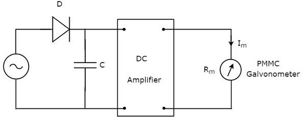
The above circuit consists of a diode, capacitor, DC amplifier and PMMC galvanometer. The diode present in the above circuit is used for rectification purpose. So, the diode converts AC voltage signal into a DC voltage signal. The capacitor charges to the peak value of this DC voltage signal.
During positive half cycle of AC voltage signal, the diode conducts and the capacitor charges to the peak value of AC voltage signal. When the value of AC voltage signal is less than this value, the diode will be reverse biased.
Thus, the capacitor will discharge through resistor of DC amplifier till the next positive half cycle of AC voltage signal. When the value of AC voltage signal is greater than the capacitor voltage, the diode conducts and the process will be repeated.
We should select the component values in such a way that the capacitor charges fast and discharges slowly. As a result, the meter always responds to this capacitor voltage, i.e. the peak value of AC voltage.
True RMS Responding AC Voltmeter
As the name suggests, the true RMS responding AC voltmeter responds to the true RMS values of AC voltage signal. This voltmeter measures RMS values of AC voltages. The circuit diagram of true RMS responding AC voltmeter is shown in below figure.
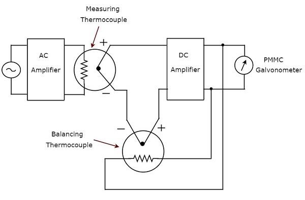
The above circuit consists of an AC amplifier, two thermocouples, DC amplifier and PMMC galvanometer. AC amplifier amplifies the AC voltage signal. Two thermocouples that are used in above circuit are a measuring thermocouple and a balancing thermocouple. Measuring thermocouple produces an output voltage, which is proportional to RMS value of the AC voltage signal.
Any thermocouple converts a square of input quantity into a normal quantity. This means there exists a non-linear relationship between the output and input of a thermocouple. The effect of non-linear behavior of a thermocouple can be neglected by using another thermocouple in the feedback circuit. The thermocouple that is used for this purpose in above circuit is known as balancing thermocouple.
The two thermocouples, namely measuring thermocouple and balancing thermocouple together form a bride at the input of DC amplifier. As a result, the meter always responds to the true RMS value of AC voltage signal.
To Continue Learning Please Login