- Electronic Measuring Instruments
- Home
- Introduction
- Performance Characteristics
- Measurement Errors
- Measuring Instruments
- DC Voltmeters
- AC Voltmeters
- Other AC Voltmeters
- DC Ammeters
- AC Ammeter
- OHMMeters
- MultiMeter
- Signal Generators
- Wave Analyzers
- Spectrum Analyzers
- Basics of Oscilloscopes
- Special Purpose Oscilloscopes
- Lissajous Figures
- CRO Probes
- Bridges
- DC Bridges
- AC Bridges
- Other AC Bridges
- Transducers
- Active Transducers
- Passive Transducers
- Measurement Of Displacement
- Data Acquisition Systems
- Useful Resources
- Quick Guide
- Useful Resources
- Discussion
MultiMeter
In previous chapters, we discussed about voltmeters, ammeters and ohmmeters. These measuring instruments are used to measure voltage, current and resistance respectively. That means, we have separate measuring instruments for measuring voltage, current and resistance.
Suppose, if a single measuring instrument can be used to measure the quantities such as voltage, current & resistance one at a time, then it is said to be multimeter. It has got the name multimeter, since it can measure multiple electrical quantities one at a time.
Measurements by using Multimeter
Multimeter is an instrument used to measure DC & AC voltages, DC & AC currents and resistances of several ranges. It is also called Electronic Multimeter or Voltage Ohm Meter (VOM).
DC voltage Measurement
The part of the circuit diagram of Multimeter, which can be used to measure DC voltage is shown in below figure.
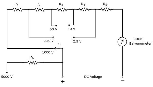
The above circuit looks like a multi range DC voltmeter. The combination of a resistor in series with PMMC galvanometer is a DC voltmeter. So, it can be used to measure DC voltages up to certain value.
We can increase the range of DC voltages that can be measured with the same DC voltmeter by increasing the resistance value. the equivalent resistance value increases, when we connect the resistors are in series.
In above circuit, we can measure the DC voltages up to 2.5V by using the combination of resistor, $R_{5}$ in series with PMMC galvanometer. By connecting a resistor, $R_{4}$ in series with the previous circuit, we can measure the DC voltages up to 10V. In this way, we can increase the range of DC voltages, simply by connecting a resistor in series with the previous (earlier) circuit.
We can measure the DC voltage across any two points of an electric circuit, by connecting the switch, S to the desired voltage range.
DC Current Measurement
The part of the circuit diagram of Multimeter, which can be used to measure DC current is shown in below figure.
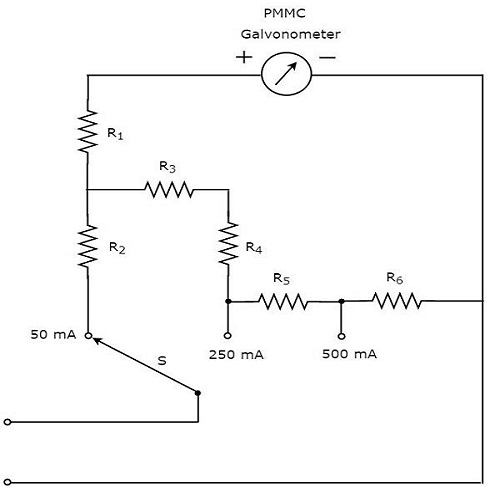
The above circuit looks like a multi range DC ammeter. the combination of a resistor in parallel with PMMC galvanometer is a DC ammeter. So, it can be used to measure DC currents up to certain value.
We can get different ranges of DC currents measured with the same DC ammeter by placing the resistors in parallel with previous resistor. In above circuit, the resistor, $R_{1}$ is connected in series with the PMMC galvanometer in order to prevent the meter gets damaged due to large current.
We can measure the DC current that is flowing through any two points of an electric circuit, by connecting the switch, S to the desired current range
AC voltage Measurement
The part of the circuit diagram of Multimeter, which can be used to measure AC voltage is shown in below figure.
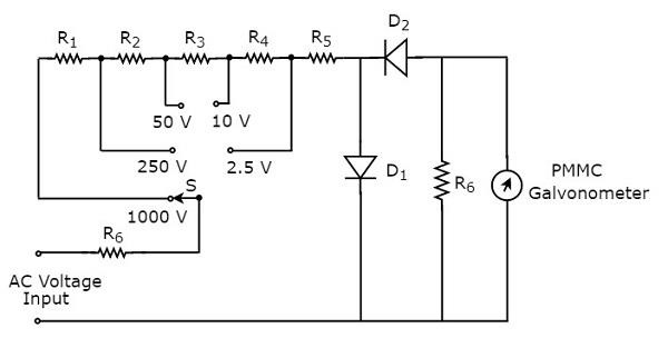
The above circuit looks like a multi range AC voltmeter. We know that, we will get AC voltmeter just by placing rectifier in series (cascade) with DC voltmeter. The above circuit was created just by placing the diodes combination and resistor, $R_{6}$ in between resistor, $R_{5}$ and PMMC galvanometer.
We can measure the AC voltage across any two points of an electric circuit, by connecting the switch, S to the desired voltage range.
Resistance Measurement
The part of the circuit diagram of Multimeter, which can be used to measure resistance is shown in below figure.
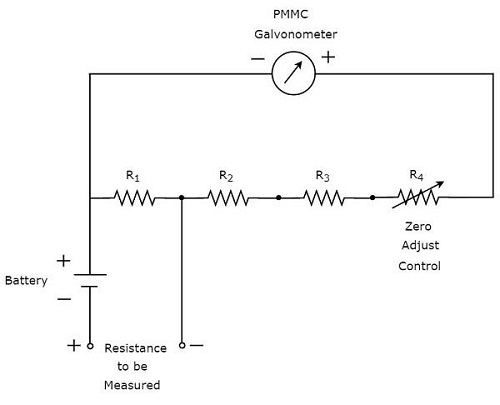
We have to do the following two tasks before taking any measurement.
- Short circuit the instrument
- Vary the zero adjust control until the meter shows full scale current. That means, meter indicates zero resistance value.
Now, the above circuit behaves as shunt ohmmeter and has the scale multiplication of 1, i.e. 100. We can also consider higher order powers of 10 as the scale multiplications for measuring high resistances.
To Continue Learning Please Login