- Wireless Communication - Home
- Wireless Communication - Overview
- Terms in Mobile Telephony
- Multiple Access
- Channel Characteristics
- Wireless Communication - TCP/IP
- Cellular Wireless Networks
- Propagation Losses
- Techniques
- Wireless Communication - WAN
- Bluetooth
- Wireless Communication - Internet
- Wireless Communication - WAP
- Wireless Communication - Satellite
Wireless Communication - Quick Guide
Wireless Communication - Overview
Wireless communication involves the transmission of information over a distance without the help of wires, cables or any other forms of electrical conductors.
Wireless communication is a broad term that incorporates all procedures and forms of connecting and communicating between two or more devices using a wireless signal through wireless communication technologies and devices.
Features of Wireless Communication
The evolution of wireless technology has brought many advancements with its effective features.
The transmitted distance can be anywhere between a few meters (for example, a television's remote control) and thousands of kilometers (for example, radio communication).
Wireless communication can be used for cellular telephony, wireless access to the internet, wireless home networking, and so on.
Other examples of applications of radio wireless technology include GPS units, garage door openers, wireless computer mice, keyboards and headsets, headphones, radio receivers, satellite television, broadcast television and cordless telephones.
Wireless - Advantages
Wireless communication involves transfer of information without any physical connection between two or more points. Because of this absence of any 'physical infrastructure', wireless communication has certain advantages. This would often include collapsing distance or space.
Wireless communication has several advantages; the most important ones are discussed below −
Cost effectiveness
Wired communication entails the use of connection wires. In wireless networks, communication does not require elaborate physical infrastructure or maintenance practices. Hence the cost is reduced.
Example − Any company providing wireless communication services does not incur a lot of costs, and as a result, it is able to charge cheaply with regard to its customer fees.
Flexibility
Wireless communication enables people to communicate regardless of their location. It is not necessary to be in an office or some telephone booth in order to pass and receive messages.
Miners in the outback can rely on satellite phones to call their loved ones, and thus, help improve their general welfare by keeping them in touch with the people who mean the most to them.
Convenience
Wireless communication devices like mobile phones are quite simple and therefore allow anyone to use them, wherever they may be. There is no need to physically connect anything in order to receive or pass messages.
Example − Wireless communications services can also be seen in Internet technologies such as Wi-Fi. With no network cables hampering movement, we can now connect with almost anyone, anywhere, anytime.
Speed
Improvements can also be seen in speed. The network connectivity or the accessibility were much improved in accuracy and speed.
Example − A wireless remote can operate a system faster than a wired one. The wireless control of a machine can easily stop its working if something goes wrong, whereas direct operation cant act so fast.
Accessibility
The wireless technology helps easy accessibility as the remote areas where ground lines cant be properly laid, are being easily connected to the network.
Example − In rural regions, online education is now possible. Educators no longer need to travel to far-flung areas to teach their lessons. Thanks to live streaming of their educational modules.
Constant connectivity
Constant connectivity also ensures that people can respond to emergencies relatively quickly.
Example − A wireless mobile can ensure you a constant connectivity though you move from place to place or while you travel, whereas a wired land line cant.
Terms in Mobile Telephony
Among the various terms used in Mobile telephony, the most used ones will be discussed here.
Mobile Station (MS) − The Mobile Station (MS) communicates the information with the user and modifies it to the transmission protocols of the air interface to communicate with the BSS. The user information communicates with the MS through a microphone and speaker for the speech, keyboard and display for short messaging and the cable connection for other data terminals. The mobile station has two elements Mobile Equipment (ME) and Subscriber Identity Module (SIM).
Mobile Equipment (ME) − ME is a piece of hardware that the customer purchases from the equipment manufacturer. The hardware piece contains all the components needed for the implementation of the protocols to interface with the user and the air-interface to the base stations.
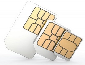
Subscriber Identity Module (SIM) − This is a smart card issued at the subscription to identify the specifications of a user such as address and type of service. The calls in the GSM are directed to the SIM rather than the terminal.
SMS are also stored in the SIM card. It carries every user's personal information which enables a number of useful applications.
Base Station (BS) − A base station transmits and receives user data. When a mobile is only responsible for its user's data transmission and reception, a base station is capable to handle the calls of several subscribers simultaneously.
Base Transceiver Station (BTS) − The user data transmission takes place between the mobile phone and the base station (BS) through the base transceiver station. A transceiver is a circuit which transmits and receives, i.e., does both.
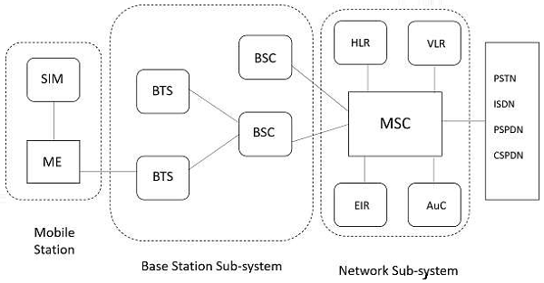
Mobile Switching Center (MSC) − MSC is the hardware part of the wireless switch that can communicate with PSTN switches using the Signaling System 7 (SS7) protocol as well as other MSCs in the coverage area of a service provider. The MSC also provides for communication with other wired and wireless networks as well as support for registration and maintenance of the connection with the mobile stations.
The following image illustrates the parts of different sub-systems. HLR, VLR, EIR and AuC are the sub-systems of Network sub-system.
Channels − It is a range of frequency allotted to particular service or systems.
Control Channel − Radio channel used for transmission of call setup, call request, call initiation and other beacon or control purposes.
Forward Control Channel(FCC) − Radio channel used for transmission of information from the base station to the mobile
Reverse Channel(RC) − Radio channel used for transmission of information from the mobile to base station.
Voice Channel(VC) − Radio channel used for voice or data transmission.
Handoff − It is defined as the transferring a call from the channel or base station to another base station.
Roamer − A mobile station which operates in a service area other than that from which service has been subscribed
Transceiver − A device capable of simultaneously transmitting and receiving radio signals.
Wireless Communication - Multiple Access
Multiple access schemes are used to allow many mobile users to share simultaneously a finite amount of radio spectrum.
Multiple Access Techniques
In wireless communication systems, it is often desirable to allow the subscriber to send information simultaneously from the mobile station to the base station while receiving information from the base station to the mobile station.
A cellular system divides any given area into cells where a mobile unit in each cell communicates with a base station. The main aim in the cellular system design is to be able to increase the capacity of the channel, i.e., to handle as many calls as possible in a given bandwidth with a sufficient level of quality of service.
There are several different ways to allow access to the channel. These includes mainly the following −
- Frequency division multiple-access (FDMA)
- Time division multiple-access (TDMA)
- Code division multiple-access (CDMA)
- Space division multiple access (SDMA)
Depending on how the available bandwidth is allocated to the users, these techniques can be classified as narrowband and wideband systems.
Narrowband Systems
Systems operating with channels substantially narrower than the coherence bandwidth are called as Narrow band systems. Narrow band TDMA allows users to use the same channel but allocates a unique time slot to each user on the channel, thus separating a small number of users in time on a single channel.
Wideband Systems
In wideband systems, the transmission bandwidth of a single channel is much larger than the coherence bandwidth of the channel. Thus, multipath fading doesnt greatly affect the received signal within a wideband channel, and frequency selective fades occur only in a small fraction of the signal bandwidth.
Frequency Division Multiple Access (FDMA)
FDMA is the basic technology for advanced mobile phone services. The features of FDMA are as follows.
- FDMA allots a different sub-band of frequency to each different user to access the network.
- If FDMA is not in use, the channel is left idle instead of allotting to the other users.
- FDMA is implemented in Narrowband systems and it is less complex than TDMA.
- Tight filtering is done here to reduce adjacent channel interference.
- The base station BS and mobile station MS, transmit and receive simultaneously and continuously in FDMA.
Time Division Multiple Access (TDMA)
In the cases where continuous transmission is not required, there TDMA is used instead of FDMA. The features of TDMA include the following.
- TDMA shares a single carrier frequency with several users where each users makes use of non-overlapping time slots.
- Data transmission in TDMA is not continuous, but occurs in bursts. Hence handsoff process is simpler.
- TDMA uses different time slots for transmission and reception thus duplexers are not required.
- TDMA has an advantage that is possible to allocate different numbers of time slots per frame to different users.
- Bandwidth can be supplied on demand to different users by concatenating or reassigning time slot based on priority.
Code Division Multiple Access (CDMA)
Code division multiple access technique is an example of multiple access where several transmitters use a single channel to send information simultaneously. Its features are as follows.
- In CDMA every user uses the full available spectrum instead of getting allotted by separate frequency.
- CDMA is much recommended for voice and data communications.
- While multiple codes occupy the same channel in CDMA, the users having same code can communicate with each other.
- CDMA offers more air-space capacity than TDMA.
- The hands-off between base stations is very well handled by CDMA.
Space Division Multiple Access (SDMA)
Space division multiple access or spatial division multiple access is a technique which is MIMO (multiple-input multiple-output) architecture and used mostly in wireless and satellite communication. It has the following features.
- All users can communicate at the same time using the same channel.
- SDMA is completely free from interference.
- A single satellite can communicate with more satellites receivers of the same frequency.
- The directional spot-beam antennas are used and hence the base station in SDMA, can track a moving user.
- Controls the radiated energy for each user in space.
Spread Spectrum Multiple Access
Spread spectrum multiple access (SSMA) uses signals which have a transmission bandwidth whose magnitude is greater than the minimum required RF bandwidth.
There are two main types of spread spectrum multiple access techniques −
- Frequency hopped spread spectrum (FHSS)
- Direct sequence spread spectrum (DSSS)
Frequency Hopped Spread Spectrum (FHSS)
This is a digital multiple access system in which the carrier frequencies of the individual users are varied in a pseudo random fashion within a wideband channel. The digital data is broken into uniform sized bursts which is then transmitted on different carrier frequencies.
Direct Sequence Spread Spectrum (DSSS)
This is the most commonly used technology for CDMA. In DS-SS, the message signal is multiplied by a Pseudo Random Noise Code. Each user is given his own code word which is orthogonal to the codes of other users and in order to detect the user, the receiver must know the code word used by the transmitter.
The combinational sequences called as hybrid are also used as another type of spread spectrum. Time hopping is also another type which is rarely mentioned.
Since many users can share the same spread spectrum bandwidth without interfering with one another, spread spectrum systems become bandwidth efficient in a multiple user environment.
Channel Characteristics
The wireless channel is susceptible to a variety of transmission impediments such as path loss, interference and blockage. These factors restrict the range, data rate, and the reliability of the wireless transmission.
Types of Paths
The extent to which these factors affect the transmission depends upon the environmental conditions and the mobility of the transmitter and receiver. The path followed by the signals to get to the receiver, are two types, such as −
Direct-path
The transmitted signal, when reaches the receiver directly, can be termed as a directpath and the components presents that are present in the signal are called as directpath components.
Multi-path
The transmitted signal when reaches the receiver, through different directions undergoing different phenomenon, such a path is termed as multi-path and the components of the transmitted signal are called as multi-path components.
They are reflected, diffracted and scattered by the environment, and arrive at the receiver shifted in amplitude, frequency and phase with respect to the direct path component.
Characteristics of Wireless Channel
The most important characteristics of wireless channel are −
- Path loss
- Fading
- Interference
- Doppler shift
In the following sections, we will discuss these channel characteristics one by one.
Path Loss
Path loss can be expressed as the ratio of the power of the transmitted signal to the power of the same signal received by the receiver, on a given path. It is a function of the propagation distance.
Estimation of path loss is very important for designing and deploying wireless communication networks
Path loss is dependent on a number of factors such as the radio frequency used and the nature of the terrain.
The free space propagation model is the simplest path loss model in which there is a direct-path signal between the transmitter and the receiver, with no atmosphere attenuation or multipath components.
In this model, the relationship between the transmitted power Pt and the received power Pr is given by
$$P_{r} = P_{t}G_{t}G_{r}(\frac{\lambda}{4\Pi d})^2$$Where
Gt is the transmitter antenna gain
Gr is the receiver antenna gain
d is the distance between the transmitter and receiver
λ is the wavelength of the signal
Two-way model also called as two path models is widely used path loss model. The free space model described above assumes that there is only one single path from the transmitter to the receiver.
In reality, the signal reaches the receiver through multiple paths. The two path model tries to capture this phenomenon. The model assumes that the signal reaches the receiver through two paths, one a line-of-sight and the other the path through which the reflected wave is received.
According to the two-path model, the received power is given by
$$P_{r} = P_{t}G_{t}G_{r}(\frac{h_{t}h_{r}}{d^2})^2$$Where
pt is the transmitted power
Gt represent the antenna gain at the transmitter
Gr represent the antenna gain at the receiver
d is the distance between the transmitter and receiver
ht is the height of the transmitter
hr are the height of the receiver
Fading
Fading refers to the fluctuations in signal strength when received at the receiver. Fading can be classified in to two types −
- Fast fading/small scale fading and
- Slow fading/large scale fading
Fast fading refers to the rapid fluctuations in the amplitude, phase or multipath delays of the received signal, due to the interference between multiple versions of the same transmitted signal arriving at the receiver at slightly different times.
The time between the reception of the first version of the signal and the last echoed signal is called delay spread. The multipath propagation of the transmitted signal, which causes fast fading, is because of the three propagation mechanisms, namely −
- Reflection
- Diffraction
- Scattering
The multiple signal paths may sometimes add constructively or sometimes destructively at the receiver causing a variation in the power level of the received signal. The received single envelope of a fast fading signal is said to follow a Rayleigh distribution to see if there is no line-of-sight path between the transmitter and the receiver.
Slow Fading
The name Slow Fading itself implies that the signal fades away slowly. The features of slow fading are as given below.
Slow fading occurs when objects that partially absorb the transmission lie between the transmitter and receiver.
Slow fading is so called because the duration of the fade may last for multiple seconds or minutes.
Slow fading may occur when the receiver is inside a building and the radio wave must pass through the walls of a building, or when the receiver is temporarily shielded from the transmitter by a building. The obstructing objects cause a random variation in the received signal power.
Slow fading may cause the received signal power to vary, though the distance between the transmitter and receiver remains the same.
Slow fading is also referred to as shadow fading since the objects that cause the fade, which may be large buildings or other structures, block the direct transmission path from the transmitter to the receiver.
Interference
Wireless transmissions have to counter interference from a wide variety of sources. Two main forms of interference are −
- Adjacent channel interference and
- Co-channel interference.
In Adjacent channel interference case, signals in nearby frequencies have components outside their allocated ranges, and these components may interfere with on-going transmission in the adjacent frequencies. It can be avoided by carefully introducing guard bands between the allocated frequency ranges.
Co-channel interference, sometimes also referred to as narrow band interference, is due to other nearby systems using the same transmission frequency.
Inter-symbol interference is another type of interference, where distortion in the received signal is caused by the temporal spreading and the consequent overlapping of individual pulses in the signal.
Adaptive equalization is a commonly used technique for combating inter symbol interference. It involves gathering the dispersed symbol energy into its original time interval. Complex digital processing algorithms are used in the equalization process.
Wireless Communication - TCP/IP
The original TCP/IP protocol was defined as four software layers built upon the hardware. Today, however, TCP/IP is thought of as a five-layer model with the layers named similar to the ones in the OSI model.
Comparison between OSI and TCP/IP Suite
When we compare the two models, we find that two layers, session and presentation, are missing from the TCP/IP protocol. The application layer in the suite is usually considered to be the combination of three layers in the OSI model.
The OSI model specifies which functions belong to each of its layers but the layers of the TCP/IP protocol suite contain relatively independent protocols that can be mixed and matched, depending on the needs of the system. The term hierarchical means that each upper level protocol is supported by one or more lower level protocols.
Layers in the TCP/IP Suite
The four layers of the TCP/IP model are the host-to-network layer, internet/network layer, transport layer and the application layer. The purpose of each layer in the TCP/IP protocol suite is detailed below.
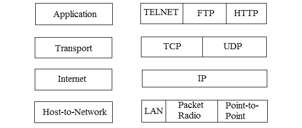
The above image represents the layers of TCP/IP protocol suite.
Physical Layer
TCP/IP does not define any specific protocol for the physical layer. It supports all of the standard and proprietary protocols.
At this level, the communication is between two hops or nodes, either a computer or router. The unit of communication is a single bit.
When the connection is established between the two nodes, a stream of bits is flowing between them. The physical layer, however, treats each bit individually.
The responsibility of the physical layer, in addition to delivery of bits, matches with what mentioned for the physical layer of the OSI model, but it mostly depends on the underlying technologies that provide links.
Data Link Layer
TCP/IP does not define any specific protocol for the data link layer either. It supports all of the standard and proprietary protocols.
At this level also, the communication is between two hops or nodes. The unit of communication however, is a packet called a frame.
A frame is a packet that encapsulates the data received from the network layer with an added header and sometimes a trailer.
The head, among other communication information, includes the source and destination of frame.
The destination address is needed to define the right recipient of the frame because many nodes may have been connected to the link.
The source address is needed for possible response or acknowledgment as may be required by some protocols.
LAN, Packet Radio and Point-to-Point protocols are supported in this layer
Network Layer
At the network layer, TCP/IP supports the Internet Protocol (IP). The Internet Protocol (IP) is the transmission mechanism used by the TCP/IP protocols.
- IP transports data in packets called datagrams, each of which is transported separately.
- Datagrams can travel along different routes and can arrive out of sequence or be duplicated.
IP does not keep track of the routes and has no facility for reordering datagrams once they arrive at their destination.
Transport Layer
There is a main difference between the transport layer and the network layer. Although all nodes in a network need to have the network layer, only the two end computers need to have the transport layer.
The network layer is responsible for sending individual datagrams from computer A to computer B; the transport layer is responsible for delivering the whole message, which is called a segment, from A to B.
A segment may consist of a few or tens of datagrams. The segments need to be broken into datagrams and each datagram has to be delivered to the network layer for transmission.
Since the Internet defines a different route for each datagram, the datagrams may arrive out of order and may be lost.
The transport layer at computer B needs to wait until all of these datagrams to arrive, assemble them and make a segment out of them.
Traditionally, the transport layer was represented in the TCP/IP suite by two protocols: User Datagram Protocol (UDP) and Transmission Control Protocol (TCP).
A new protocol called Stream Control Transmission Protocol (SCTP) has been introduced in the last few years.
Application Layer
The application layer in TCP/IP is equivalent to the combined session, presentation, and application layers in the OSI model.
The application layer allows a user to access the services of our private internet or the global Internet.
Many protocols are defined at this layer to provide services such as electronic mail file transfer, accessing the World Wide Web, and so on.
The protocols supported in this layer are TELNET, FTP and HTTP.
Cellular Wireless Networks
Cellular network is an underlying technology for mobile phones, personal communication systems, wireless networking etc. The technology is developed for mobile radio telephone to replace high power transmitter/receiver systems. Cellular networks use lower power, shorter range and more transmitters for data transmission.
Features of Cellular Systems
Wireless Cellular Systems solves the problem of spectral congestion and increases user capacity. The features of cellular systems are as follows −
Offer very high capacity in a limited spectrum.
Reuse of radio channel in different cells.
Enable a fixed number of channels to serve an arbitrarily large number of users by reusing the channel throughout the coverage region.
Communication is always between mobile and base station (not directly between mobiles).
Each cellular base station is allocated a group of radio channels within a small geographic area called a cell.
Neighboring cells are assigned different channel groups.
By limiting the coverage area to within the boundary of the cell, the channel groups may be reused to cover different cells.
Keep interference levels within tolerable limits.
Frequency reuse or frequency planning.
Organization of Wireless Cellular Network.
Cellular network is organized into multiple low power transmitters each 100w or less.
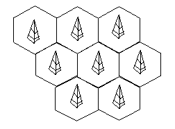
Shape of Cells
The coverage area of cellular networks are divided into cells, each cell having its own antenna for transmitting the signals. Each cell has its own frequencies. Data communication in cellular networks is served by its base station transmitter, receiver and its control unit.
The shape of cells can be either square or hexagon −
Square
A square cell has four neighbors at distance d and four at distance Root 2 d
- Better if all adjacent antennas equidistant
- Simplifies choosing and switching to new antenna
Hexagon
A hexagon cell shape is highly recommended for its easy coverage and calculations. It offers the following advantages −
- Provides equidistant antennas
- Distance from center to vertex equals length of side
Frequency Reuse
Frequency reusing is the concept of using the same radio frequencies within a given area, that are separated by considerable distance, with minimal interference, to establish communication.
Frequency reuse offers the following benefits −
- Allows communications within cell on a given frequency
- Limits escaping power to adjacent cells
- Allows re-use of frequencies in nearby cells
- Uses same frequency for multiple conversations
- 10 to 50 frequencies per cell
For example, when N cells are using the same number of frequencies and K be the total number of frequencies used in systems. Then each cell frequency is calculated by using the formulae K/N.
In Advanced Mobile Phone Services (AMPS) when K = 395 and N = 7, then frequencies per cell on an average will be 395/7 = 56. Here, cell frequency is 56.
Propagation Losses
Antenna and Wave propagation plays a vital role in wireless communication networks. An antenna is an electrical conductor or a system of conductors that radiates/collects (transmits or receives) electromagnetic energy into/from space. An idealized isotropic antenna radiates equally in all directions.
Propagation Mechanisms
Wireless transmissions propagate in three modes. They are −
- Ground-wave propagation
- Sky-wave propagation
- Line-of-sight propagation
Ground wave propagation follows the contour of the earth, while sky wave propagation uses reflection by both earth and ionosphere.
Line of sight propagation requires the transmitting and receiving antennas to be within the line of sight of each other. Depending upon the frequency of the underlying signal, the particular mode of propagation is followed.
Examples of ground wave and sky wave communication are AM radio and international broadcasts such as BBC. Above 30 MHz, neither ground wave nor sky wave propagation operates and the communication is through line of sight.
Transmission Limitations
In this section, we will discuss the various limitations that affect electromagnetic wave transmissions. Let us start with attenuation.
Attenuation
The strength of signal falls with distance over transmission medium. The extent of attenuation is a function of distance, transmission medium, as well as the frequency of the underlying transmission.
Distortion
Since signals at different frequencies attenuate to different extents, a signal comprising of components over a range of frequencies gets distorted, i.e., the shape of the received signal changes.
A standard method of resolving this problem (and recovering the original shape) is to amplify higher frequencies and thus equalize attenuation over a band of frequencies.
Dispersion
Dispersion is the phenomenon of spreading of a burst of electromagnetic energy during propagation. Bursts of data sent in rapid succession tend to merge due to dispersion.
Noise
The most pervasive form of noise is thermal noise, which is often modeled using an additive Gaussian model. Thermal noise is due to thermal agitation of electrons and is uniformly distributed across the frequency spectrum.
Other forms of noise include −
Inter modulation noise (caused by signals produced at frequencies that are sums or differences of carrier frequencies)
Crosstalk (interference between two signals)
Impulse noise (irregular pulses of high energy caused by external electromagnetic disturbances).
While an impulse noise may not have a significant impact on analog data, it has a noticeable effect on digital data, causing burst errors.
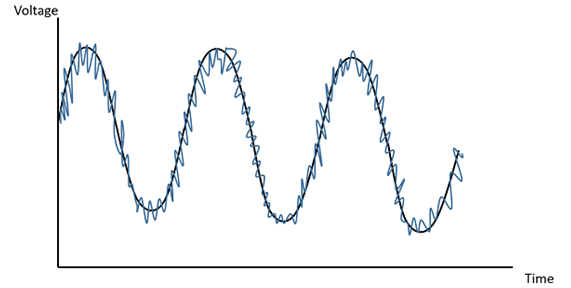
The above figure clearly illustrates how the noise signal overlaps the original signal and tries to change its characteristics.
Fading
Fading refers to the variation of the signal strength with respect to time/distance and is widely prevalent in wireless transmissions. The most common causes of fading in the wireless environment are multipath propagation and mobility (of objects as well as the communicating devices).
Multipath propagation
In wireless media, signals propagate using three principles, which are reflection, scattering, and diffraction.
Reflection occurs when the signal encounters a large solid surface, whose size is much larger than the wavelength of the signal, e.g., a solid wall.
Diffraction occurs when the signal encounters an edge or a corner, whose size is larger than the wavelength of the signal, e.g., an edge of a wall.
Scattering occurs when the signal encounters small objects of size smaller than the wavelength of the signal.
One consequence of multipath propagation is that multiple copies of a signal propagation along multiple different paths, arrive at any point at different times. So the signal received at a point is not only affected by the inherent noise, distortion, attenuation, and dispersion in the channel but also the interaction of signals propagated along multiple paths.
Delay spread
Suppose we transmit a probing pulse from a location and measure the received signal at the recipient location as a function of time. The signal power of the received signal spreads over time due to multipath propagation.
The delay spread is determined by the density function of the resulting spread of the delay over time. Average delay spread and root mean square delay spread are the two parameters that can be calculated.
Doppler spread
This is a measure of spectral broadening caused by the rate of change of the mobile radio channel. It is caused by either relative motion between the mobile and base station or by the movement of objects in the channel.
When the velocity of the mobile is high, the Doppler spread is high, and the resulting channel variations are faster than that of the baseband signal, this is referred to as fast fading. When channel variations are slower than the baseband signal variations, then the resulting fading is referred to as slow fading.
Wireless Communication - Techniques
In some cases, there is a scope of performance deterioration, which affects the output. The major cause for this might be the mobile channel impairments. To resolve this, there are three popular techniques −
Equalizer
An equalizer within a receiver compensates for the average range of expected channel amplitude and delay characteristics. In other words, an equalizer is a filter at the mobile receiver whose impulse response is inverse of the channel impulse response. Such equalizers find their use in frequency selective fading channels.
Diversity
Diversity is another technique used to compensate fast fading and is usually implemented using two or more receiving antennas. It is usually employed to reduce the depths and duration of the fades experienced by a receiver in a flat fading channel.
Channel Coding
Channel coding improves mobile communication link performance by adding redundant data bits in the transmitted message. At the baseband portion of the transmitter, a channel coder maps a digital message sequence in to another specific code sequence containing greater number of bits than original contained in the message. Channel Coding is used to correct deep fading or spectral null.
Equalization
ISI (Inter Symbol Interference) has been identified as one of the major obstacles to high speed data transmission over mobile radio channels. If the modulation bandwidth exceeds the coherence bandwidth of the radio channel (i.e., frequency selective fading), modulation pulses are spread in time, causing ISI.
An equalizer at the front end of a receiver compensates for the average range of expected channel amplitude and delay characteristics. As the mobile fading channels are random and time varying, equalizers must track the time-varying characteristics of the mobile channel and therefore should be time varying or adaptive. An adaptive equalizer has two phases of operation: training and tracking.
Training Mode
Initially a known, fixed length training sequence is sent by the transmitter so that the receiver equalizer may average to a proper setting. Training sequence is typically a pseudo-random binary signal or a fixed, of prescribed bit pattern.
The training sequence is designed to permit an equalizer at the receiver to acquire the proper filter coefficient in the worst possible channel condition. An adaptive filter at the receiver thus uses a recursive algorithm to evaluate the channel and estimate filter coefficients to compensate for the channel.
Tracking Mode
When the training sequence is finished the filter coefficients are near optimal. Immediately following the training sequence, user data is sent.
When the data of the users are received, the adaptive algorithms of the equalizer tracks the changing channel. As a result, the adaptive equalizer continuously changes the filter characteristics over time.
Diversity
Diversity is a powerful communication receiver technique that provides wireless link improvement at a relatively low cost. Diversity techniques are used in wireless communications systems to primarily to improve performance over a fading radio channel.
In such a system, the receiver is provided with multiple copies of the same information signal which are transmitted over two or more real or virtual communication channels. Thus the basic idea of diversity is repetition or redundancy of information. In virtually all the applications, the diversity decisions are made by the receiver and are unknown to the transmitter.
Types of Diversity
Fading can be classified into small scale and large scale fading. Small-scale fades are characterized by deep and rapid amplitude fluctuations which occur as the mobile moves over distances of just a few wavelengths. For narrow-band signals, this typically results in a Rayleigh faded envelope. In order to prevent deep fades from occurring, microscopic diversity techniques can exploit the rapidly changing signal.
If the antenna elements of the receiver are separated by a fraction of the transmitted wavelength, then the various copies of the information signal or generically termed as branches, can be combined suitably or the strongest of them can be chosen as the received signal. Such a diversity technique is termed as Antenna or Space diversity.
Frequency Diversity
The same information signal is transmitted on different carriers, the frequency separation between them being at least the coherence bandwidth.
Time Diversity
The information signal is transmitted repeatedly in time at regularly intervals. The separation between the transmit times should be greater than the coherence time, Tc. The time interval depends on the fading rate, and increases with the decrease in the rate of fading.
Polarization diversity
Here, the electric and magnetic fields of the signal carrying the information are modified and many such signals are used to send the same information. Thus orthogonal type of polarization is obtained.
Angle Diversity
Here, directional antennas are used to create independent copies of the transmitted signal over multiple paths.
Space Diversity
In Space diversity, there are multiple receiving antennas placed at different spatial locations, resulting in different (possibly independent) received signals.
The difference between the diversity schemes lies in the fact that in the first two schemes, there is wastage of bandwidth due to duplication of the information signal to be sent. Thus problem is avoided in the remaining three schemes, but with the cost of increased antenna complexity.
The correlation between signals as a function of distance between the antenna elements is given by the relation −
$$\rho = J_0^2 \lgroup\frac{2\Pi d}{\lambda}\rgroup$$Where,
J0 = Bessel function of zero order and first kind
d = distance of separation in space of antenna elements
λ = carrier wavelength.
Wireless Communication - WAN
In the field of computers, the wide usage of group connections have become inevitable, which lead to the introduction of LANs (Local Area Networks). These LANs come under the category of small scale networks within a single building or campus.
WANs are Wide Area Networks which cover a wider area such a city, or a limited area greater than LAN. Wireless Personal Area Networks (PANs) are the next step down from WLANs, covering smaller areas with low power transmission, for networking of portable and mobile computing devices such as PCs, Personal Digital Assistants (PDAs).
Fundamentals of WLANs
The technical issues in WLANs must be understood in order to appreciate the difference between wired networks and wireless networks. The use of WLANs and their design goals are then studied. The types of WLANS, their components and their basic functionalities are also detailed.
IEEE 802.11 Standard
This section introduces a prominent standard ion WLANs, the IEEE 802.11 standard. The medium access control (MAC) layer and the physical layer mechanisms are explained. This section also covers some of the optional functionalities such as security and quality of service (QoS).
HIPERLAN Standard
This section describes another WLAN standard, HIPERLAN standard, which is a European standard based on radio access.
Bluetooth
This section deals with the Bluetooth standard, which enables personal devices to communicate with each other in the absence of infrastructure.
WLAN Fundamentals
While both portable terminals and mobile terminals can move from one place to another, portable terminals are accessed only when they are stationary.
Mobile Terminals (MTs), on the other hand, are more powerful, and can be accessed when they are in motion. WLANs aim to support truly mobile work stations.
WLAN Uses
Wireless computer networks are capable of offering versatile functionalities. WLANs are very flexible and can be configured in a variety of topologies based on the application. Some possible uses of WLANs are described below.
Users would be able to surf the Internet, check e-mail, and receive Instant Messages on the move.
In areas affected by earthquakes or other disasters, no suitable infrastructure may be available on the site. WLANs are handy in such locations to set up networks on the fly.
There are many historic buildings where there has been a need to set up computer networks. In such places, wiring may not be permitted or the building design may not be conductive to efficient wiring. WLANs are very good solutions in such places.
Design Goals
The following are some of the goals which have to be achieved while designing WLANs −
Operational simplicity − Design of wireless LANS must incorporate features to enable a mobile user to quickly set up and access network services in a simple and efficient manner.
Power efficient operation − The power-constrained nature of mobile computing devices such as laptops and PDAs necessitates the important requirement of WLANs operating with minimal power consumption. Therefore, the design of WLAN must incorporate power-saving features and use appropriate technologies and protocols to achieve this.
License-free operation − One of the major factors that affects the cost of wireless access is the license fee for the spectrum in which a particular wireless access technology operates. Low cost of access is an important aspect for popularizing a WLAN technology. Hence the design of WLAN should consider the parts of the frequency spectrum. For its operation which does not require an explicit
Tolerance to interference − The proliferation of different wireless networking technologies both for civilian and military applications have led to a significant increase in the interference level across the radio spectrum.
The WLAN design should account for this and take appropriate measures by way of selecting technologies and protocols to operate in the presence of interference.
Global Usability − The design of the WLAN, the choice of technology, and the selection of the operating frequency spectrum should take into account the prevailing spectrum restriction in countries across the world. This ensures the acceptability of the technology across the world.
Security − The inherent broadcast nature of wireless medium adds to the requirement of security features to be included in the design of WLAN technology.
Safety requirements − The design of WLAN technology should follow the safety requirements that can be classified into the following.
- Interference to medical and other instrumentation devices.
- Increased power level of transmitters that can lead to health hazards.
A well-designed WLAN should follow the power emission restrictions that are applicable in the given frequency spectrum.
Quality of service requirements − Quality of Service (QoS) refers to the provisioning of designated levels of performance for multimedia traffic. The design of WLAN should take into consideration the possibility of supporting a wide variety of traffic, including multimedia traffic.
Compatibility with other technologies and applications − The interoperability among different LANS is important for efficient communication between hosts operating with different LAN technologies.
Network Architecture
Network architecture describes the types of WLANs, the components of a typical WLAN and the services offered by a WLAN.
Infrastructure based versus Ad Hoc LANs
WLANs can be broadly classified into two types, namely Infrastructure networks and Ad hoc LANs, based on the underlying architecture.
Infrastructure networks
Infrastructure networks contain special nodes called Access Points (APs), which are connected via existing networks.
- APs are special in the sense that they can interact with wireless nodes as well as with the existing wired network.
- The other wireless nodes, also known as Mobile stations (STAs), communicate via APs.
- The APs also act as bridges with other networks.
Ad hoc LANs
Ad hoc LANs do not need any fixed infrastructure. These networks can be set up on the fly at any place. Nodes communicate directly with each other for forward messages through other nodes that are directly accessible.
Wireless Communication - Bluetooth
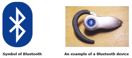
Bluetooth wireless technology is a short range communications technology intended to replace the cables connecting portable unit and maintaining high levels of security. Bluetooth technology is based on Ad-hoc technology also known as Ad-hoc Pico nets, which is a local area network with a very limited coverage.
History of Bluetooth
WLAN technology enables device connectivity to infrastructure based services through a wireless carrier provider. The need for personal devices to communicate wirelessly with one another without an established infrastructure has led to the emergence of Personal Area Networks (PANs).
Ericsson's Bluetooth project in 1994 defines the standard for PANs to enable communication between mobile phones using low power and low cost radio interfaces.
In May 1988, Companies such as IBM, Intel, Nokia and Toshiba joined Ericsson to form the Bluetooth Special Interest Group (SIG) whose aim was to develop a defacto standard for PANs.
IEEE has approved a Bluetooth based standard named IEEE 802.15.1 for Wireless Personal Area Networks (WPANs). IEEE standard covers MAC and Physical layer applications.
Bluetooth specification details the entire protocol stack. Bluetooth employs Radio Frequency (RF) for communication. It makes use of frequency modulation to generate radio waves in the ISM band.
The usage of Bluetooth has widely increased for its special features.
Bluetooth offers a uniform structure for a wide range of devices to connect and communicate with each other.
Bluetooth technology has achieved global acceptance such that any Bluetooth enabled device, almost everywhere in the world, can be connected with Bluetooth enabled devices.
Low power consumption of Bluetooth technology and an offered range of up to ten meters has paved the way for several usage models.
Bluetooth offers interactive conference by establishing an adhoc network of laptops.
Bluetooth usage model includes cordless computer, intercom, cordless phone and mobile phones.
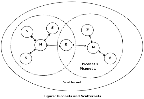
Piconets and Scatternets
Bluetooth enabled electronic devices connect and communicate wirelessly through shortrange devices known as Piconets. Bluetooth devices exist in small ad-hoc configurations with the ability to act either as master or slave the specification allows a mechanism for master and slave to switch their roles. Point to point configuration with one master and one slave is the simplest configuration.
When more than two Bluetooth devices communicate with one another, this is called a PICONET. A Piconet can contain up to seven slaves clustered around a single master. The device that initializes establishment of the Piconet becomes the master.
The master is responsible for transmission control by dividing the network into a series of time slots amongst the network members, as a part of time division multiplexing scheme which is shown below.
The features of Piconets are as follows −
Within a Piconet, the timing of various devices and the frequency hopping sequence of individual devices is determined by the clock and unique 48-bit address of master.
Each device can communicate simultaneously with up to seven other devices within a single Piconet.
Each device can communicate with several piconets simultaneously.
Piconets are established dynamically and automatically as Bluetooth enabled devices enter and leave piconets.
There is no direct connection between the slaves and all the connections are essentially master-to-slave or slave-to-master.
Slaves are allowed to transmit once these have been polled by the master.
Transmission starts in the slave-to-master time slot immediately following a polling packet from the master.
A device can be a member of two or more piconets, jumping from one piconet to another by adjusting the transmission regime-timing and frequency hopping sequence dictated by the master device of the second piconet.
It can be a slave in one piconet and master in another. It however cannot be a master in more than once piconet.
Devices resident in adjacent piconets provide a bridge to support inner-piconet connections, allowing assemblies of linked piconets to form a physically extensible communication infrastructure known as Scatternet.
Spectrum
Bluetooth technology operates in the unlicensed industrial, scientific and medical (ISM) band at 2.4 to 2.485 GHZ, using a spread spectrum hopping, full-duplex signal at a nominal rate of 1600 hops/sec. the 2.4 GHZ ISM band is available and unlicensed in most countries.
Range
Bluetooth operating range depends on the device Class 3 radios have a range of up to 1 meter or 3 feet Class 2 radios are most commonly found in mobile devices have a range of 10 meters or 30 feet Class 1 radios are used primarily in industrial use cases have a range of 100 meters or 300 feet.
Data rate
Bluetooth supports 1Mbps data rate for version 1.2 and 3Mbps data rate for Version 2.0 combined with Error Data Rate.
Wireless Communication - Internet
The advent of the Internet has caused a revolutionary change in the use of computers and the search for information. The Internet has affected the traditional way of information exchange and now almost every city, every town, and every street has access to the Internet.
Homes, schools and businesses connect to the Internet today using a variety of different methods. One method, wireless Internet service, provides Internet access to customers without the need for underground copper, fiber, or other forms of commercial network cabling. Compared to more established wired services like DSL and cable Internet, wireless technology brings added convenience and mobility to computer networks.
The below sections describe each popular type of wireless Internet service available.
Satellite Internet
Introduced in the mid1990s, satellite became the first mainstream consumer wireless Internet service. Compared to other forms of wireless Internet service, satellite enjoys the advantage of availability. Requiring only a small dish antenna, satellite modem and subscription plan, satellite works in almost all rural areas not serviced by other technologies.
However, satellite also offers relatively low performing wireless Internet. Satellite suffers from high latency (delay) connections due to the long distance signals must travel between Earth and the orbiting stations. Satellite also supports relatively modest amounts of network bandwidth.
Public Wi-Fi Networks
Some municipalities have built their public wireless Internet service using Wi-Fi technology. These so-called mesh networks join numerous wireless access points together to span larger urban areas. Individual Wi-Fi hotspots also provide public wireless Internet service in select locations.
Wi-Fi is a low-cost option relative to other forms of wireless Internet service. Equipment is inexpensive (many newer computers have the needed hardware built in), and Wi-Fi hotspots remains free in some locales.
Fixed Wireless Broadband
Fixed wireless is a type of broadband that utilizes mounted antennas pointed at radio transmission towers.
Mobile Broadband
Cell phones have existed for decades, but only recently have cellular networks evolved to become a mainstream form of wireless Internet service. With an installed cellular network adapter, or by tethering a cell phone to a laptop computer, Internet connectivity can be maintained in any area with cell tower coverage. Mobile broadband service will not function without having an Internet data subscription in place from some provider.
The classical wired networks have given rise to a number of application protocols such as TELNET, FTP and SMTP. The wireless application protocol (WAP) architecture aims at bridging the gap at the application level, between the wireless users and the services offered to them.
Wireless Internet
Wireless Internet refers to the extension of the services offered by the Internet to mobile users, enabling them to access information and data irrespective of their location. The inherent problems associated with wireless domain, mobility of nodes, and the design of existing protocols used in the Internet, require several solutions for making the wireless Internet a reality.
The major issues that are to be considered for Wireless Internet are the following −
- Address mobility
- Inefficiency of transport layer protocols and
- Inefficiency of application layer protocols
Address Mobility
The network layer protocol used in the Internet is Internet Protocol (IP) which was designed for wired networks with fixed nodes. IP employs a hierarchical addressing with a globally unique 32-bit address which has two parts Network identifier and Host identifier.
The network identifier refers to the subnet address to which the host is connected. The addressing scheme was used to reduce the routing table size in the core routers of the Internet, which uses only the network part of the IP address for making routing decisions.
This addressing scheme may not work directly in the wireless extension of the Internet, as the mobile hosts may move from one subnet to another, but the packets addressed to the mobile host may be delivered to the old subnet to which the node was originally attached.
Inefficiency of Transport Layer Protocols
The transport layer is very important in the Internet and it ensures setting up and maintaining end-to-end connections, reliable end-to-end delivery of data packets, flow control and congestion control. TCP is the predominant transport layer protocol for wired networks, even though UDP, a connectionless unreliable transport layer protocol is used by certain applications.
Wireless Internet requires efficient operation of the transport layer protocols as the wireless medium is inherently unreliable due to its time varying and environment dependent characteristics. Traditional TCP invokes a congestion control algorithm in order to handle congestion in the networks. If a data packet or an ACK packet is lost, then TCP assumes that the loss is due to congestion and reduces the size of the congestion window by half.
With every successive packet loss, the congestion window is reduced, and hence TCP provides a degraded performance in wireless links. Even in situations where the packet loss is caused by link error or collision, the TCP invokes the congestion control algorithm leading to very low throughput.
The identification of the real cause that led to the packet loss is important in improving the performance of the TCP over wireless links. Some of the solutions for the transport layer issues include −
- Indirect TCP (ITCP)
- Snoop TCP and
- Mobile TCP
Inefficiency of Application Layer Protocols
Traditional application layer protocols used in the Internet such as HTTP, TELNET, simple mail transfer protocol (SMTP), and several markup languages such as HTML were designed and optimized for wired networks. Many of these protocols are not very efficient when used with wireless links.
The major issues that prevent HTTP from being used in Wireless Internet are its stateless operation, high overhead due to character encoding, redundant information carried in the HTTP requests, and opening of a new TCP connection with every transaction.
The capabilities of the handheld devices are limited, making it difficult to handle computationally and bandwidth wise expensive application protocols. Wireless application protocol (WAP) and optimizations over traditional HTTP are some of the solutions for the application layer issues.
Wireless Communication - WAP
WAP stands for Wireless Application Protocol. WAP represents a suite of protocols rather than a single protocol. WAP aims at integrating a simple lightweight browser also known as a micro-browser into handheld devices, thus requiring minimal amounts of resources such as memory and CPU at these devices.
WAP tries to compensate for the shortfalls of the wireless handheld devices and the wireless link by incorporating more intelligence into the network nodes such as the routers, web servers, and BSs.
The primary objectives of the WAP protocol suite are the following.
- Independence from the wireless network standards
- Interoperability among service providers
- Overcoming the shortfalls of the wireless medium
- Overcoming the drawbacks of handheld devices
- Increasing efficiency and reliability
- Providing security, scalability, and extensibility
The WAP Model
WAP adopts a client-server approach. It specifies a proxy server that acts as an interface between the wireless domain and core wired network. This proxy server, also known as a WAP gateway, is responsible for a wide variety of functions such as protocol translation and optimizing data transfer over the wireless medium.
Wireless network parts consist of −
- Content provider (Application or origin server)
- Mobile device (WAP client)
- WAP gateway
- WAP proxy
The WAP Architecture has been designed to closely follow the web. The only difference is the presence of the WAP gateway is translating between HTTP and WAP.
WAP Client
The three sections to be mentioned regarding WAP client are WAE user agent, WTA user agent and WAP stack.
WAE user agent − Wireless application environment user agent is the browser that renders the content for display.
WTA user agent − Wireless telephony application agent receives compiled WTA files from WTA server and executes them.
WAP stack − WAP stack allows the phone to connect to the WAP gateway using the WAP Protocols.
Application Server
The element in the network where the information (web, WAP) applications reside are WAP proxy, WAP gateway or WAP server −
Proxy − This is an intermediary element acting both as a client and as a server in the network it is located between client and server. The client sends requests to it and it retrieves and caches the information needed by contacting the origin Server.
Gateway − This is an intermediary element usually used to connect two different types of networks.
WAP Gateway is basically software that is placed between a network that supports WAP and IP packet network such as Internet.
The WAP Protocol Stack
WAP protocol stack is shown in the following figure −
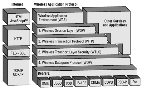
Application Layer
The application layer provides an application environment intended for the development and execution of portable application and services WAE consists of two different user agents located on client side.
The WAE user agent consists of browser and the text message editor along with the WTA user agent.
Session Layer
The session layer supplies methods for the organized exchange of content between Client/Service applications.
WAP contains the following components −
Connection Oriented Session Services − These operate over WTP.
Connectionless Session Services − These operate directly over WDP.
Session services − These functionalities help to set up a connection between a client and server using primitive messages.
Primitives messages are defined as messages that client sends to the server to request a service facility. The client sends request primitives and receive confirm primitive and the server can send response primitives and receive indication primitives.
The connectionless session service provides only non-confirmed service. To start session, the client invokes a WSP primitives that provide some parameters, such as the server address, client address and client headers. In some respects, WSP is basically a binary form of HTTP.
Transaction Layer
Provides different methods for performing transaction to varying degree of reliability.
Security Layer
Optional layer that provides, when authentication, privacy and secure connection is present, between applications. It is based on SSL (Secure Socket Layer). It provides services that ensure privacy, server authentication, client authentication and data integrity.
A Standard SSL session is opened between the web server and the WAP gateway, and WTLS session is initialized between the gateway and the mobile device. The encrypted content is send through this connection from the server to the gateway, which translates it and sends it to mobile phone. The transaction between SSL and WTLS takes place in the memory of the WAP gateway.
Transport Layer
This is the bottom layer, connected with the bearer service offered by the operator. Bearer services are the communication between the mobile phone and the base stations. They include SMS, CSD, USSD, GSM, GPRS, DECT, CDMA, FDMA, and TDMA.
The physical layer prepares the data to be sent from the mobile device over the air services and sends the data using bearer service implemented in the network that the device is operating in. WDP has an interface with various bearer networks, so it must have a bearer specific implementation. WDP is the only layer that must be rewritten to support different bearer networks. The WTP layer implements a simple request-response transaction oriented protocol instead of the three-way-handshake connection mechanism.
Wireless Communication - Satellite
A satellite is an object that revolves around another object. For example, earth is a satellite of The Sun, and moon is a satellite of earth.
A communication satellite is a microwave repeater station in a space that is used for telecommunication, radio and television signals. A communication satellite processes the data coming from one earth station and it converts the data into another form and send it to the second earth station.
How a Satellite Works
Two stations on earth want to communicate through radio broadcast but are too far away to use conventional means. The two stations can use a relay station for their communication. One earth station transmits the signal to the satellite.
Uplink frequency is the frequency at which ground station is communicating with satellite. The satellite transponder converts the signal and sends it down to the second earth station, and this is called Downlink frequency. The second earth station also communicates with the first one in the same way.
Advantages of Satellite
The advantages of Satellite Communications are as follows −
- The Coverage area is very high than that of terrestrial systems.
- The transmission cost is independent of the coverage area.
- Higher bandwidths are possible.
Disadvantages of Satellite
The disadvantages of Satellite Communications are as follows −
- Launching satellites into orbits is a costly process.
- The bandwidths are gradually used up.
- High propagation delay for satellite systems than the conventional terrestrial systems.
Satellite Communication Basics
The process of satellite communication begins at an earth station. Here an installation is designed to transmit and receive signals from a satellite in orbit around the earth. Earth stations send information to satellites in the form of high powered, high frequency (GHz range) signals.
The satellites receive and retransmit the signals back to earth where they are received by other earth stations in the coverage area of the satellite. Satellite's footprint is the area which receives a signal of useful strength from the satellite.
The transmission system from the earth station to the satellite through a channel is called the uplink. The system from the satellite to the earth station through the channel is called the downlink.
Satellite Frequency Bands
The satellite frequency bands which are commonly used for communication are the Cband, Ku-band, and Ka-band. C-band and Ku-band are the commonly used frequency spectrums by today's satellites.
It is important to note that there is an inverse relationship between frequency and wavelength i.e. when frequency increases, wavelength decreases this helps to understand the relationship between antenna diameter and transmission frequency. Larger antennas (satellite dishes) are necessary to gather the signal with increasing wavelength.
Earth Orbits
A satellite when launched into space, needs to be placed in certain orbit to provide a particular way for its revolution, so as to maintain accessibility and serve its purpose whether scientific, military or commercial. Such orbits which are assigned to satellites, with respect to earth are called as Earth Orbits. The satellites in these orbits are Earth Orbit Satellites.
The important kinds of Earth Orbits are −
- Geo-synchronous Earth Orbit
- Geo-stationary Earth Orbit
- Medium Earth Orbit
- Low Earth Orbit
Geo-synchronous Earth Orbit (GEO) Satellites
A Geo-synchronous Earth orbit Satellite is one which is placed at an altitude of 22,300 miles above the Earth. This orbit is synchronized with a side real day (i.e., 23hours 56minutes). This orbit can have inclination and eccentricity. It may not be circular. This orbit can be tilted at the poles of the earth. But it appears stationary when observed from the Earth.
The same geo-synchronous orbit, if it is circular and in the plane of equator, it is called as geo-stationary orbit. These Satellites are placed at 35,900kms (same as geosynchronous) above the Earths Equator and they keep on rotating with respect to earths direction (west to east). These satellites are considered stationary with respect to earth and hence the name implies.
Geo-Stationary Earth Orbit Satellites are used for weather forecasting, satellite TV, satellite radio and other types of global communications.
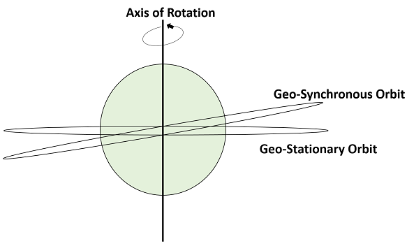
The above figure shows the difference between Geo-synchronous and Geo- Stationary orbits. The Axis of rotation indicates the movement of Earth.
The main point to note here is that every Geo-Stationary orbit is a Geo-Synchronous orbit. But every Geo-Synchronous orbit is NOT a Geo-stationary orbit.
Medium Earth Orbit (MEO) Satellites
Medium earth orbit (MEO) satellite networks will orbit at distances of about 8000 miles from earth's surface. Signals transmitted from a MEO satellite travel a shorter distance. This translates to improved signal strength at the receiving end. This shows that smaller, more lightweight receiving terminals can be used at the receiving end.
Since the signal is travelling a shorter distance to and from the satellite, there is less transmission delay. Transmission delay can be defined as the time it takes for a signal to travel up to a satellite and back down to a receiving station.
For real-time communications, the shorter the transmission delay, the better will be the communication system. As an example, if a GEO satellite requires 0.25 seconds for a round trip, then MEO satellite requires less than 0.1 seconds to complete the same trip. MEOs operates in the frequency range of 2 GHz and above.
Low Earth Orbit (LEO) Satellites
The LEO satellites are mainly classified into three categories namely, little LEOs, big LEOs, and Mega-LEOs. LEOs will orbit at a distance of 500 to 1000 miles above the earth's surface.
This relatively short distance reduces transmission delay to only 0.05 seconds. This further reduces the need for sensitive and bulky receiving equipment. Little LEOs will operate in the 800 MHz (0.8 GHz) range. Big LEOs will operate in the 2 GHz or above range, and Mega-LEOs operates in the 20-30 GHz range.
The higher frequencies associated with Mega-LEOs translates into more information carrying capacity and yields to the capability of real-time, low delay video transmission scheme.
High Altitude Long Endurance (HALE) Platforms
Experimental HALE platforms are basically highly efficient and lightweight airplanes carrying communications equipment. This will act as very low earth orbit geosynchronous satellites.
These crafts will be powered by a combination of battery and solar power or high efficiency turbine engines. HALE platforms will offer transmission delays of less than 0.001 seconds at an altitude of only 70,000 feet, and even better signal strength for very lightweight hand-held receiving devices.
Orbital Slots
Here there may arise a question that with more than 200 satellites up there in geosynchronous orbit, how do we keep them from running into each other or from attempting to use the same location in space? To answer this problem, international regulatory bodies like the International Telecommunications Union (ITU) and national government organizations like the Federal Communications Commission (FCC) designate the locations on the geosynchronous orbit where the communications satellites can be located.
These locations are specified in degrees of longitude and are called as orbital slots. The FCC and ITU have progressively reduced the required spacing down to only 2 degrees for C-band and Ku-band satellites due to the huge demand for orbital slots.
