
Article Categories
- All Categories
-
 Data Structure
-
 Networking
-
 RDBMS
RDBMS
-
 Operating System
-
 Java
Java
-
 MS Excel
-
 iOS
iOS
-
 HTML
HTML
-
 CSS
CSS
-
 Android
-
 Python
-
 C Programming
-
 C++
C++
-
 C#
C#
-
 MongoDB
-
 MySQL
MySQL
-
 Javascript
-
 PHP
PHP
-
 Economics & Finance
What is IBM 370 I/0 Channel?
The I/O processor in the IBM 370 computer is known as a channel. A general computer system configuration contains multiple channels with each channel connected to one or more I/O devices.
There are three types of channels including a multiplexer, selector, and block-multiplexer. The multiplexer channel can be linked to multiple slow and medium-speed devices and is adequate for operating with several I/O devices together.
The selector channel is created to manage one I/O operation at a time and is generally used to control one high-speed device. The block-multiplexer channel merges the features of both the multiplexer and selector channels. It supports a connection to several high-speed devices, but all I/O transfers are controlled with a full block of data as distinguished to a multiplexer channel, which can share only one byte at a time.
The CPU interacts directly with the channels through dedicated control lines and indirectly through reserved storage areas in memory. The diagram shows the word formats related to the channel operation.
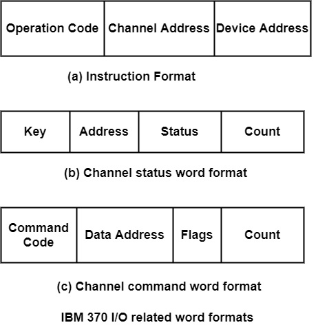
The I/O instruction format has three fields: operation code, channel address, and device address. The computer system can have multiple channels, and each is created an address. Similarly, each channel can be linked to multiple devices and each device has created an address. The operation code determines one of eight I/O instructions: start I/O, start I/O fast release, test I/O, clear I/O, halt I/O, halt device, test channel, and save channel identification.
The addressed channel acknowledges each of the I/O instructions and implements them. It also sets one of four condition codes in a processor register known as PSW (processor status word). The CPU can test the condition code in the PSW to specify the result of the I/O operation.
The format of the channel status word is displayed in figure (b). It is continually saved in location 64 in memory. The key field is a protection mechanism that can avoid unauthorized access by one user to data that belongs to another client or the operating framework. The address field in the status word provides the address of the last command word used by the channel.
The difference between the start I/O and start I/O fast free instructions is that the latter needed less CPU time for its implementation. When the channel accepts one of these two instructions, it defines memory location 72 for the address of the first channel command word (CCW).
The format of the channel command word is shown in figure(c). The data address field determines the first address of a memory buffer and the count field provides the multiple bytes included in the transfer. The command field determines an I/O operation and the flag bits support additional data for the channel.

1K+ Views
