 Data Structure
 Networking
 RDBMS
RDBMS Operating System
 Java
Java MS Excel
 iOS
iOS HTML
HTML CSS
CSS Android
 Python
 C Programming
 C++
C++ C#
C# MongoDB
 MySQL
MySQL Javascript
 PHP
PHP
- Selected Reading
- UPSC IAS Exams Notes
- Developer's Best Practices
- Questions and Answers
- Effective Resume Writing
- HR Interview Questions
- Computer Glossary
- Who is Who
What is an ETHERNET in the Computer Network?
Ethernet is a LAN architecture developed by XEROX and extended by DEC, IC and Xerox. It is specified by IEEE 802.3, and it defines two categories.
These categories are as follows−
- Baseband
- Broadband
Baseband uses digital signals, while broadband uses analog signals. Baseband is further divided into five standard names as follows −
- 10 Base 5
- 10 Base 2
- 10 Base T
- 1 Base 5
- 100 Base T
The first numbers used in all standards, i.e., 10, 1, 100, indicate the data rate in Mbps, while the last numbers 2, 5, and letter T indicate the maximum cable length or type of cable. Only one specification is defined for broadband, and that is 10 Broad 36. 10 Base 5 means a data rate of 10 Mbps and cable length restriction of 500 meters.
The network uses Carrier-sense multiple access with collision detection (CSMA/CD) technique. When multiple users access a single line, there is always a chance of overlapping and destroying data called collisions. Thus, if traffic increases on a single line, there are always chances of collision.
The carrier senses several access with collision Detection (ICMP/CD) is a technique that can help detect a collision, quits the current transmission and retransmission of data and takes place after waiting for some predetermined time to get the line cleared.
Electrical Signification for Ethernet
There are various electrical significations for Ethernet, which are as follows:
Signaling
Baseband system uses Manchester digital encoding while the broadband system uses differential PSK.
Data Rate
The Ethernet LANs supports a data rate between 1 Mbps to 100 Mbps. Baseband defines 1, 10, and 100 Mbps data rates, while broadband defines a data rate of 10 Mbps.
Frame Format
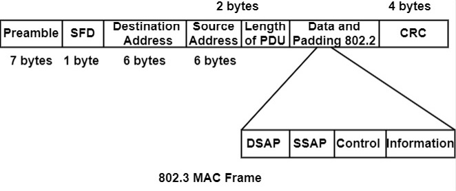
IEEE 802.3 specifies only one type of frame format that includes seven fields. These fields are as follows−
- Preamble − It contains seven bytes (56 bits) and is used for synchronization.
- Start frame delimiter (SFD) − It is a one-byte field and is used to signal the frame's beginning.
- Destination Address and Source Address fields are six bytes' fields containing sender and receiver address as declared by the Network Interface Card.
- The next field length/type is a two-byte field and indicates the number of PDU bits and its type. It provides a base for other protocols.
- The PDU or 802.2 frames contain the entire 802.2 frames as a modular removable unit. It can start from the 46th byte and can continue up to the 1500th byte. It is generated by the LLC sublayer depending on the size and type of the PDU, and then it is linked to an 802.3 frame.
- The last field is CRC, which contains error detection information.
The frame format is demonstrated in the figure


