- Data Comm & Networks Home
- DCN - Overview
- DCN - What is Computer Network
- DCN - Uses of Computer Network
- DCN - Computer Network Types
- DCN - Network LAN Technologies
- DCN - Computer Network Models
- DCN - Computer Network Security
- DCN - Components
- DCN - Connectors
- DCN - Switches
- DCN - Repeaters
- DCN - Gateways
- DCN - Bridges
- DCN - Socket
- DCN - Network Interface Card
- DCN - NIC: Pros and Cons
- DCN - Network Hardware
- DCN - Network Port
- Computer Network Topologies
- DCN - Computer Network Topologies
- DCN - Point-to-point Topology
- DCN - Bus Topology
- DCN - Star Topology
- DCN - Ring Topology
- DCN - Mesh Topology
- DCN - Tree Topology
- DCN - Hybrid Topology
- Physical Layer
- DCN - Physical Layer Introduction
- DCN - Digital Transmission
- DCN - Analog Transmission
- DCN - Transmission media
- DCN - Wireless Transmission
- DCN - Transmission Impairments
- DCN - Multiplexing
- DCN - Network Switching
- DCN - Circuit Switching
- DCN - Packet Switching
- DCN - Message Switching
- Data Link Layer
- DCN - Data Link Layer Introduction
- DCN - Data Link Control & Protocols
- DCN - RMON
- DCN - Token Ring Network
- DCN - Hamming Code
- DCN - Byte Stuffing
- DCN - Channel Allocation
- DCN - MAC Address
- DCN - Address Resolution Protocol
- DCN - Cyclic Redundancy Checks
- DCN - Error Control
- DCN - Flow Control
- DCN - Framing
- DCN - Error Detection & Correction
- DCN - Error Correcting Codes
- DCN - Parity Bits
- Network Layer
- DCN - Network Layer Introduction
- DCN - Network Addressing
- DCN - Routing
- DCN - Routing Table
- DCN - Internetworking
- DCN - Network Layer Protocols
- DCN - Routing Information Protocol
- DCN - Border Gateway Protocol
- DCN - OSPF Protocol
- DCN - Network Address Translation
- DCN - Network Address Translation Types
- Transport Layer
- DCN - Transport Layer Introduction
- DCN - Transmission Control Protocol
- DCN - User Datagram Protocol
- DCN - Congestion Control
- DCN - Open Loop Congestion Control
- DCN - Closed Loop Congestion Control
- DCN - Congestion Control Algorithms
- DCN - Token Bucket Algorithm
- DCN - TCP Tahoe Algorithm
- DCN - TCP Reno Algorithm
- DCN - TCP New Reno Algorithm
- DCN - TCP BIC Algorithm
- DCN - TCP CUBIC Algorithm
- DCN - TCP Service Model
- DCN - TLS Handshake
- DCN - TCP Vs. UDP
- Application Layer
- DCN - Application Layer Introduction
- DCN - Client-Server Model
- DCN - Application Protocols
- DCN - Network Services
- DCN - Virtual Private Network
- DCN - Load Shedding
- DCN - Optimality Principle
- DCN - Service Primitives
- DCN - Services of Network Security
- DCN - Hypertext Transfer Protocol
- DCN - File Transfer Protocol
- DCN - Secure Socket Layer
- Network Protocols
- DCN - ALOHA Protocol
- DCN - Pure ALOHA Protocol
- DCN - Sliding Window Protocol
- DCN - Stop and Wait Protocol
- DCN - Link State Routing
- DCN - Link State Routing Protocol
- Network Algorithms
- DCN - Shortest Path Algorithm
- DCN - Routing Algorithm
- DCN - Leaky Bucket Algorithm
- Wireless Networks
- DCN - Wireless Networks
- DCN - Wireless LANs
- DCN - Wireless LAN & IEEE 802.11
- DCN - IEEE 802.11 Wireless LAN Standards
- DCN - IEEE 802.11 Networks
- Multiplexing
- DCN - Multiplexing & Its Types
- DCN - Time Division Multiplexing
- DCN - Synchronous TDM
- DCN - Asynchronous TDM
- DCN - Synchronous Vs. Asynchronous TDM
- DCN - Frequency Division Multiplexing
- DCN - TDM Vs. FDM
- DCN - Code Division Multiplexing
- DCN - Wavelength Division Multiplexing
- Miscellaneous
- DCN - Shortest Path Routing
- DCN - B-ISDN Reference Model
- DCN - Design Issues For Layers
- DCN - Selective-repeat ARQ
- DCN - Flooding
- DCN - E-Mail Format
- DCN - Cryptography
- DCN - Unicast, Broadcast, & Multicast
- DCN - Network Virtualization
- DCN - Flow Vs. Congestion Control
- DCN - Asynchronous Transfer Mode
- DCN - ATM Networks
- DCN - Synchronous Vs. Asynchronous Transmission
- DCN - Network Attacks
- DCN - WiMax
- DCN - Buffering
- DCN - Authentication
- DCN Useful Resources
- DCN - Quick Guide
- DCN - Useful Resources
- DCN - Discussion
Transmission Impairments in Computer Networks
Transmission Impairments
Transmission impairment occurs when the received signal is different from the transmitted signal. As we know, a signal can be transmitted as Analog signal or it can be transmitted as a digital signal.
In Analog signals due to transmission impairment the resulting received signal gets different amplitude or the shape. In the case of digitally transmitted signals at the receiver side we get changes in bits (0's or 1's).
Causes of Transmission Impairments
There are various causes of transmission impairments
- Noise
- Distortion
- Attenuation
Let us understand them one by one.
Noise
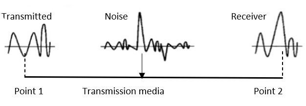
Noise is the major factor for the transmission distortion as any unwanted signal gets added to the transmitted signal by which the resulting transmitted signal gets modified and at the receiver side it is difficult to remove the unwanted noise signal. These noises are various kinds like shot noise, impulse noise, thermal noise etc.
Noise is diagrammatically represented as follows

Distortion
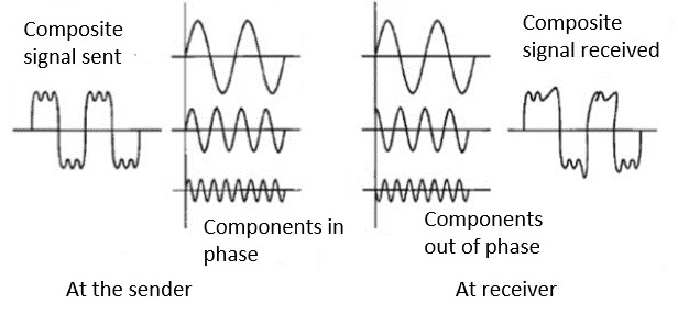
This kind of distortion is mainly appearing in case of composite signals in which a composite signal has various frequency components in it and each frequency component has some time constraint which makes a complete signal.
But while transmitting this composite signal, if a certain delay happens between the frequencies components, then there may be the chance that the frequency component will reach the receiver end with a different delay constraint from its original which leads to the change in shape of the signal. The delay happens due to environmental parameters or from the distance between transmitter and receiver etc.
Distortion is diagrammatically represented as follows

Attenuation
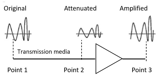
Attenuation is generally decreased in signal strength, by which the received signal will be difficult to receive at the receiver end. This attenuation happens due to the majority factor by environment as environment imposes a lot of resistance and the signal strength decreases as it tries to overcome the resistance imposed.

The above picture shows that the signal loses power at its travels time.
Attenuation is diagrammatically represented as follows
