
Article Categories
- All Categories
-
 Data Structure
-
 Networking
-
 RDBMS
RDBMS
-
 Operating System
-
 Java
Java
-
 MS Excel
-
 iOS
iOS
-
 HTML
HTML
-
 CSS
CSS
-
 Android
-
 Python
-
 C Programming
-
 C++
C++
-
 C#
C#
-
 MongoDB
-
 MySQL
MySQL
-
 Javascript
-
 PHP
PHP
-
 Economics & Finance
Types of Voltage Regulators – Linear, Zener Diode and Shunt
A voltage regulator is an electronic circuit which is used to control the variations in the output voltage of a power supply so that it will remain within the suitable limits. Since, in the case of practical circuits, the voltage changes due to several reasons such as change in input voltage, change in temperature of the circuit components, etc. But, ideally, the voltage output of the power supply should be in a certain range that is acceptable for the connected circuit. This is achieved by using a circuit called voltage regulator.
In this article, we will discuss the different types of voltage regulators. But before we will understand the basic meaning of the term voltage regulator.
What is a Voltage Regulator?
As the name implies, a voltage regulator is an electronic circuit that regulates the voltage when there is any change in the input voltage and other circuit conditions like temperature. As we know, most practical circuit needs a steady voltage to function efficiently, but due to various reasons the voltage of the power supply may vary and may damage the circuit. Hence, a voltage regulator acts as a protective shield for devices.
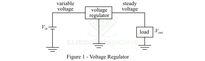
The voltage regulator converts a fluctuating voltage into a stable voltage, and this process is termed as voltage regulation. The block diagram of a voltage regulator is shown in Figure-1.
Types of Voltage Regulators
The following are the major types of voltage regulators used in different electronic devices ?
- Linear Voltage Regulator
- Zener Diode Voltage Regulator
- Shunt Voltage Regulator
Let us discuss each of these three voltage regulators one by one.
Linear Voltage Regulator
The type of voltage regulator that uses a FET (Field Effect Transistor) controlled by a negative feedback circuit to produce a steady output voltage irrespective of the variations in the input voltage and load current is known as a linear voltage regulator. It is also known as Low-Dropout Linear Regulator (LDO).
A typical linear voltage regulator works as a voltage divider circuit, i.e. it produces a steady output voltage by varying the resistance of the voltage regulator with respect to the load resistance. A typical linear voltage regulator is shown in Figure-2.
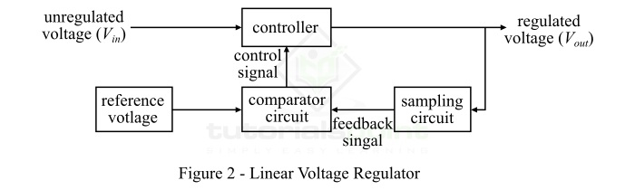
From the block diagram, it is clear that the unregulated voltage is input to the controller of the regulator which controls the magnitude of the input voltage and gives an output voltage. Also, the output voltage is sampled by using a sampling circuit and is fed to the comparator circuit. The sampled voltage is compared with the reference voltage. If there is any difference between the sampled voltage and reference voltage, then an error signal is produced and is fed back to the control to adjust the output voltage to the desired value.
Zener Diode Voltage Regulator
A zener diode is a heavily doped semiconductor diode that is designed to operate in the reverse bias mode. In electronic circuits, the zener diode is used as a voltage regulator because it can maintain a constant voltage across the load.
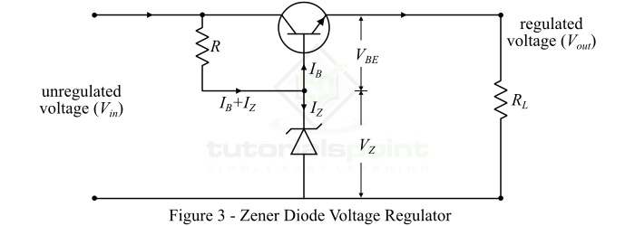
The circuit diagram of a typical zener diode voltage regulator is shown in Figure-3. In the zener diode voltage regulator, a series pass transistor is used in emitter follower. For this reason, it is also known as zener controlled transistor series voltage regulator or emitter follower voltage regulator.
In the case of zener diode voltage regulator, the emitter and collector terminals of the transistor are connected in series with respect to the load. Here, the variable element is the transistor and the zener diode supplies the reference voltage to the circuit. Therefore, the output voltage of the zener diode voltage regulator is given by,
$$\mathrm{V_{O}=V_{Z}+V_{BE}}$$
Shunt Voltage Regulator
The type of voltage regulator in which the regulating element shunts a portion of the total current to ground is referred to as a shunt voltage regulator. The shunt voltage regulator uses the surplus current to maintain a constant voltage across the load. The shunt voltage regulator is one of the most essential part of a linear power supply.
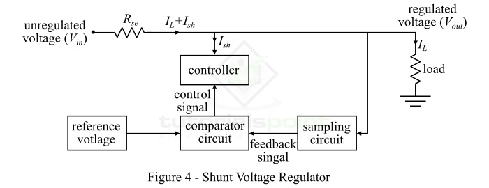
The circuit diagram of a shunt voltage regulator is shown in Figure-4. In the case of shunt voltage regulator, the comparator circuit provide a control signal to the controller, wherever there is a fluctuation (increase or decrease) in the output voltage due to any variation in the input voltage and load current. In this situation, the controller circuit will shunt the extra portion of the total current from the load so a constant voltage can be maintained across the load.
Applications of Voltage Regulators
Following are some of the important applications of voltage regulators ?
Voltage regulators are used in computer power supplies.
Voltage regulators are used in electric power distribution systems.
Voltage regulators are also used in power generating plants, etc.
Voltage regulators are used automobile alternators to produce a constant voltage for changing the battery.
Conclusion
Voltage regulators are the essential elements of different electronic devices such as computer SMPS, automobile alternators, etc. It maintains the voltage across load terminals to a constant value so that the variations in the voltage do not cause damages to the load circuit or device.

2K+ Views
