
Article Categories
- All Categories
-
 Data Structure
-
 Networking
-
 RDBMS
RDBMS
-
 Operating System
-
 Java
Java
-
 MS Excel
-
 iOS
iOS
-
 HTML
HTML
-
 CSS
CSS
-
 Android
-
 Python
-
 C Programming
-
 C++
C++
-
 C#
C#
-
 MongoDB
-
 MySQL
MySQL
-
 Javascript
-
 PHP
PHP
-
 Economics & Finance
Voltage to Current Converters – Definition, Circuit, Types
In electrical and electronic circuits, there are two basic electrical quantities namely current and voltage. Sometimes, we need to convert these two quantities into one another. For this, electronic circuits are designed which are known as converters. Based on conversion, there are two types of converters namely Voltage to Current Converter (V to I Converter) and Current to Voltage Converter (I to V Converter).
In this article, we will discuss the definition, circuit diagram, types, and applications of voltage to current converters (or V to I Converters). So let?s begin with the basic introduction of the voltage to current converter.
What is a Voltage to Current Converter?
An electronic circuit that takes voltage as the input and produces a current as the output is known as a voltage to current converter. The voltage to current converter is also known as V to I converter.
In other words, an electronic circuit that produces a current which is directly proportional to the applied voltage is known as a voltage to current converter (V to I converter).
The voltage to current converters are used in instrumentation circuits. Where, the voltage to current converter produces a current corresponding to the input voltage. Therefore, it can convert electrical data from voltage to current form. The block diagram of a voltage to current converter is shown in Figure-1.

Transfer Ratio of Voltage to Current Converter
The ratio of the output current to the input voltage of a voltage to current converter is known as the transfer ratio of the converter.
$$\mathrm{Transfer\: Ratio,\: A=\frac{Output\: Current\left ( I_{out} \right )}{Input\: Voltage\left ( V_{in} \right )}}$$
Circuit Diagram of Voltage to Current Converter
A voltage to current converter can be implemented using an operational amplifier. In practice, IC LM741 operational amplifier is often used for this purpose. The operational amplifier can convert a voltage signal into a corresponding current signal.
The circuit diagram of a typical voltage to current converter using Op-Amp is shown in Figure-2.
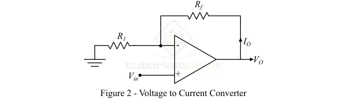
In the voltage to current converter using Op-Amp, an input voltage signal is applied at the non-inverting terminal of the Op-Amp, while the output current is taken through the output terminal.
Types of Voltage to Current Converters
There are two types of voltage to current converters which are implemented using Op-Amp ?
- Floating Load Voltage to Current Converter
- Ground Load Voltage to Current Converter
Let us discuss each of these two types of voltage to current converters one by one in detail.
Floating Load Voltage to Current Converter
As the name implies, the type of voltage to current converter in which the load resistor remains floating in the converter circuit is known as a floating load voltage to current converter. Here, the "floating load" means the load resistor is not connected to the ground. The circuit diagram of a floating load voltage to current converter is shown in Figure-3.
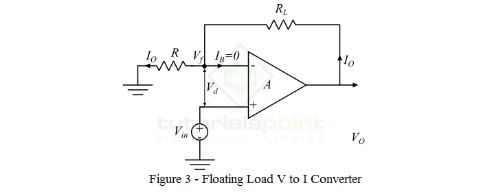
In the floating load voltage to current converter, the input voltage (Vin) is provided at the noninverting terminal of the operational amplifier (Op-Amp), whereas the inverting terminal of the Op-Amp is supplied with the feedback voltage (Vf). The feedback voltage is determined by the output current. In this type of voltage to current converter, the feedback voltage (Vf) is in series with the input difference voltage (Vd). For this reason, the floating load voltage to current converter is also known as the current series negative feedback amplifier.
The voltage equation of the floating load voltage to current converter is obtained by applying KVL in the input loop as
$$\mathrm{V_{in}=V_{d}+V_{f}}$$
The transfer function or gain of the Op-Amp (A) is very large. Thus, Vd = 0.
$$\mathrm{\therefore V_{in}=V_{f}}$$
Since the input current IB to the Op-Amp is zero.
$$\mathrm{\therefore V_{in}=I_{o}\times R}$$
Thus, the output current is
$$\mathrm{I_{o} =\frac{V_{in}}{R} }$$
Hence, from the above equation, it is clear that the output current depends upon the input voltage and input resistance of the circuit. Since, the output current is controlled by the resistor R, hence,
$$\mathrm{I_{o} \propto V_{in} }$$
i.e., the output current is directly proportional to the input voltage of the circuit.
Ground Load Voltage to Current Converter
In the ground load voltage to current converter, one end of the load resistor RL is always connected to the ground. The ground load voltage to current converter is also known as Howland Current Converter. The circuit diagram of this voltage to current converter is shown in Figure-4.
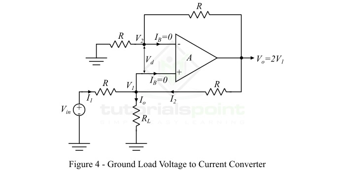
In order to analyze the circuit of the ground load voltage to current converter, we first determine the relationship between the input voltage ??? and the output current ??. For that, we apply KVL at the node ?1, and get,
$$\mathrm{I_{1}+I_{2} = I_{o}}$$
$$\mathrm{\Rightarrow \frac{V_{in}-V_{1}}{R}+\frac{V_{o}-V_{1}}{R}=I_{o}}$$
$$\mathrm{V_{in}+V_{o}-2V_{1}=I_{o}R}$$
But, for a non-inverting amplifier, the transfer gain A is
$$\mathrm{A=1+\left ( \frac{R_{f}}{R_{1}} \right )}$$
In this circuit,
$$\mathrm{R_{f}=R_{1}=R}$$
$$\mathrm{\therefore A=1+\frac{R}{R}=2}$$
Thus, the voltage at the output terminal is,
$$\mathrm{V_{o}=2V_{1}}$$
Thus, the above voltage equation of the ground load voltage to current converter will become,
$$\mathrm{V_{in}+2V_{1}-2V_{1}=I_{o}R}$$
$$\mathrm{\therefore V_{in}=I_{o}R}$$
Hence, the output load current is,
$$\mathrm{ I_{o}=\frac{V_{in}}{R}}$$
Thus, it is clear that the output current is related to the input voltage Vin and the resistor R.
Conclusion
In this article, we discussed Voltage to Current Converters in detail. Voltage to current converters are used for testing LEDs and diodes. They are also used in low-voltage AC and DC voltmeters and zener diode testers.

32K+ Views
