- Sinusoidal Oscillators - Home
- Oscillators - Introduction
- Oscillators - Basic Concepts
- Oscillators - Oscillator Circuit
- Tuned Circuit Oscillators
- Oscillators - Hartley Oscillator
- Oscillators - Colpitts Oscillator
- Oscillators - Clapp Oscillator
- Oscillators - Phase Shift Oscillators
- Wien Bridge Oscillator
- Oscillators - Crystal Oscillators
- Negative Resistance Oscillators
- Oscillators - Tunnel Diode Oscillator
- Sinusoidal Oscillators - Quick Guide
- Sinusoidal Oscillators - Resources
- Sinusoidal Oscillators - Discussion
Tunnel Diode Oscillator
The oscillator circuit that is built using a tunnel diode is called as a Tunnel diode oscillator. If the impurity concentration of a normal PN junction is highly increased, this Tunnel diode is formed. It is also known as Esaki diode, after its inventor.
Tunnel Diode
When the impurity concentration in a diode increases, the width of depletion region decreases, extending some extra force to the charge carriers to cross the junction. When this concentration is further increased, due to less width of the depletion region and the increased energy of the charge carriers, they penetrate through the potential barrier, instead of climbing over it. This penetration can be understood as Tunneling and hence the name, Tunnel diode.
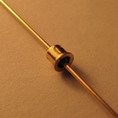
The following image shows how a practical tunnel diode looks like.
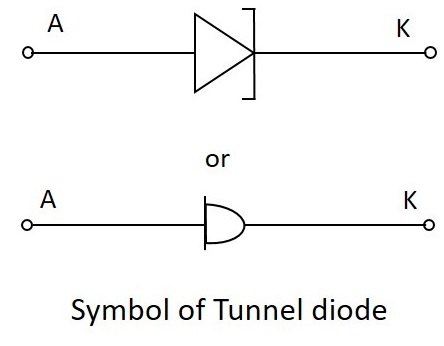
The symbols of tunnel diode are as shown below.
For more details regarding tunnel diodes, please refer our Basic Electronics tutorial.
Tunnel Diode Oscillator
The tunnel diode helps in generating a very high frequency signal of nearly 10GHz. A practical tunnel diode circuit may consist of a switch S, a resistor R and a supply source V, connected to a tank circuit through a tunnel diode D.
Working
The value of resistor selected should be in such a way that it biases the tunnel diode in the midway of the negative resistance region. The figure below shows the practical tunnel diode oscillator circuit.
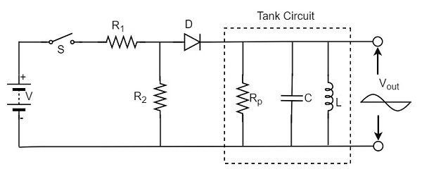
In this circuit, the resistor R1 sets proper biasing for the diode and the resistor R2 sets proper current level for the tank circuit. The parallel combination of resistor Rp inductor L and capacitor C form a tank circuit, which resonates at the selected frequency.
When the switch S is closed, the circuit current rises immediately towards the constant value, whose value is determined by the value of resistor R and the diode resistance. However, as the voltage drop across the tunnel diode VD exceeds the peak-point voltage Vp, the tunnel diode is driven into negative resistance region.
In this region, the current starts decreasing, till the voltage VD becomes equal to the valleypoint voltage Vv. At this point, a further increase in the voltage VD drives the diode into positive resistance region. As a result of this, the circuit current tends to increase. This increase in circuit will increase the voltage drop across the resistor R which will reduce the voltage VD.
V-I characteristic curve
The following graph shows the V-I characteristics of a tunnel diode −
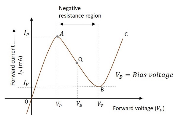
The curve AB indicates the negative resistance region as the resistance decreases while the voltage increases. It is clear that the Q-point is set at the middle of the curve AB. The Q-point can move between the points A and B during the circuit operation. The point A is called peak point and the point B is called valley point.
During the operation, after reaching the point B, the increase in circuit current will increase the voltage drop across the resistor R which will reduce the voltage VD. This brings the diode back into negative resistance region.
The decrease in voltage VD is equal to the voltage VP and this completes one cycle of operation. The continuation of these cycles produces continuous oscillations which give a sinusoidal output.
Advantages
The advantages of a tunnel diode oscillator are as follows −
- It has high switching speeds.
- It can handle high frequencies.
Disadvantages
The disadvantages of a tunnel diode oscillator are as follows −
- They are low power devices.
- Tunnel diodes are a bit costly.
Applications
The applications of a tunnel diode oscillator are as follows −
- It is used in relaxation oscillators.
- It is used in microwave oscillators.
- It is also used as Ultra high speed switching device.
- It is used as logic memory storage device.
After having covered all the major sinusoidal oscillator circuits, it is to be noted that there are many oscillators like the ones mentioned till now. The oscillators which produce sine waveforms are sinusoidal oscillators as discussed.
The oscillators which produce non-sinusoidal waveforms (rectangular, sweep, triangular etc.) are non-sinusoidal oscillators which we have discussed in detail in our Pulse Circuits tutorial.
