- Sinusoidal Oscillators - Home
- Oscillators - Introduction
- Oscillators - Basic Concepts
- Oscillators - Oscillator Circuit
- Tuned Circuit Oscillators
- Oscillators - Hartley Oscillator
- Oscillators - Colpitts Oscillator
- Oscillators - Clapp Oscillator
- Oscillators - Phase Shift Oscillators
- Wien Bridge Oscillator
- Oscillators - Crystal Oscillators
- Negative Resistance Oscillators
- Oscillators - Tunnel Diode Oscillator
- Sinusoidal Oscillators - Quick Guide
- Sinusoidal Oscillators - Resources
- Sinusoidal Oscillators - Discussion
Colpitts Oscillator
A Colpitts oscillator looks just like the Hartley oscillator but the inductors and capacitors are replaced with each other in the tank circuit. The constructional details and operation of a colpitts oscillator are as discussed below.
Construction
Let us first take a look at the circuit diagram of a Colpitts oscillator.
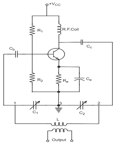
The resistors R1, R2 and Re provide necessary bias condition for the circuit. The capacitor Ce provides a.c. ground thereby providing any signal degeneration. This also provides temperature stabilization.
The capacitors Cc and Cb are employed to block d.c. and to provide an a.c. path. The radio frequency choke (R.F.C) offers very high impedance to high frequency currents which means it shorts for d.c. and opens for a.c. Hence it provides d.c. load for collector and keeps a.c. currents out of d.c. supply source.
Tank Circuit
The frequency determining network is a parallel resonant circuit which consists of variable capacitors C1 and C2 along with an inductor L. The junction of C1 and C2 are earthed. The capacitor C1 has its one end connected to base via Cc and the other to emitter via Ce. the voltage developed across C1 provides the regenerative feedback required for the sustained oscillations.
Operation
When the collector supply is given, a transient current is produced in the oscillatory or tank circuit. The oscillatory current in the tank circuit produces a.c. voltage across C1 which are applied to the base emitter junction and appear in the amplified form in the collector circuit and supply losses to the tank circuit.
If terminal 1 is at positive potential with respect to terminal 3 at any instant, then terminal 2 will be at negative potential with respect to 3 at that instant because terminal 3 is grounded. Therefore, points 1 and 2 are out of phase by 180o.
As the CE configured transistor provides 180o phase shift, it makes 360o phase shift between the input and output voltages. Hence, feedback is properly phased to produce continuous Undamped oscillations. When the loop gain |βA| of the amplifier is greater than one, oscillations are sustained in the circuit.
Frequency
The equation for frequency of Colpitts oscillator is given as
$$f = \frac{1}{2 \pi \sqrt{LC_T}}$$
CT is the total capacitance of C1 and C2 connected in series.
$$\frac{1}{C_T} = \frac{1}{C_1} + \frac{1}{C_2}$$
$$C_T = \frac{C_1 \times C_2}{C_1 + C_2}$$
Advantages
The advantages of Colpitts oscillator are as follows −
- Colpitts oscillator can generate sinusoidal signals of very high frequencies.
- It can withstand high and low temperatures.
- The frequency stability is high.
- Frequency can be varied by using both the variable capacitors.
- Less number of components are sufficient.
- The amplitude of the output remains constant over a fixed frequency range.
The Colpitts oscillator is designed to eliminate the disadvantages of Hartley oscillator and is known to have no specific disadvantages. Hence there are many applications of a colpitts oscillator.
Applications
The applications of Colpitts oscillator are as follows −
- Colpitts oscillator can be used as High frequency sinewave generator.
- This can be used as a temperature sensor with some associated circuitry.
- Mostly used as a local oscillator in radio receivers.
- It is also used as R.F. Oscillator.
- It is also used in Mobile applications.
- It has got many other commercial applications.
