- Sinusoidal Oscillators - Home
- Oscillators - Introduction
- Oscillators - Basic Concepts
- Oscillators - Oscillator Circuit
- Tuned Circuit Oscillators
- Oscillators - Hartley Oscillator
- Oscillators - Colpitts Oscillator
- Oscillators - Clapp Oscillator
- Oscillators - Phase Shift Oscillators
- Wien Bridge Oscillator
- Oscillators - Crystal Oscillators
- Negative Resistance Oscillators
- Oscillators - Tunnel Diode Oscillator
- Sinusoidal Oscillators - Quick Guide
- Sinusoidal Oscillators - Resources
- Sinusoidal Oscillators - Discussion
Crystal Oscillators
Whenever an oscillator is under continuous operation, its frequency stability gets affected. There occur changes in its frequency. The main factors that affect the frequency of an oscillator are
- Power supply variations
- Changes in temperature
- Changes in load or output resistance
In RC and LC oscillators the values of resistance, capacitance and inductance vary with temperature and hence the frequency gets affected. In order to avoid this problem, the piezo electric crystals are being used in oscillators.
The use of piezo electric crystals in parallel resonant circuits provide high frequency stability in oscillators. Such oscillators are called as Crystal Oscillators.
Crystal Oscillators
The principle of crystal oscillators depends upon the Piezo electric effect. The natural shape of a crystal is hexagonal. When a crystal wafer is cur perpendicular to X-axis, it is called as X-cut and when it is cut along Y-axis, it is called as Y-cut.
The crystal used in crystal oscillator exhibits a property called as Piezo electric property. So, let us have an idea on piezo electric effect.
Piezo Electric Effect
The crystal exhibits the property that when a mechanical stress is applied across one of the faces of the crystal, a potential difference is developed across the opposite faces of the crystal. Conversely, when a potential difference is applied across one of the faces, a mechanical stress is produced along the other faces. This is known as Piezo electric effect.
Certain crystalline materials like Rochelle salt, quartz and tourmaline exhibit piezo electric effect and such materials are called as Piezo electric crystals. Quartz is the most commonly used piezo electric crystal because it is inexpensive and readily available in nature.
When a piezo electric crystal is subjected to a proper alternating potential, it vibrates mechanically. The amplitude of mechanical vibrations becomes maximum when the frequency of alternating voltage is equal to the natural frequency of the crystal.
Working of a Quartz Crystal
In order to make a crystal work in an electronic circuit, the crystal is placed between two metal plates in the form of a capacitor. Quartz is the mostly used type of crystal because of its availability and strong nature while being inexpensive. The ac voltage is applied in parallel to the crystal.
The circuit arrangement of a Quartz Crystal will be as shown below −
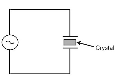
If an AC voltage is applied, the crystal starts vibrating at the frequency of the applied voltage. However, if the frequency of the applied voltage is made equal to the natural frequency of the crystal, resonance takes place and crystal vibrations reach a maximum value. This natural frequency is almost constant.
Equivalent circuit of a Crystal
If we try to represent the crystal with an equivalent electric circuit, we have to consider two cases, i.e., when it vibrates and when it doesnt. The figures below represent the symbol and electrical equivalent circuit of a crystal respectively.
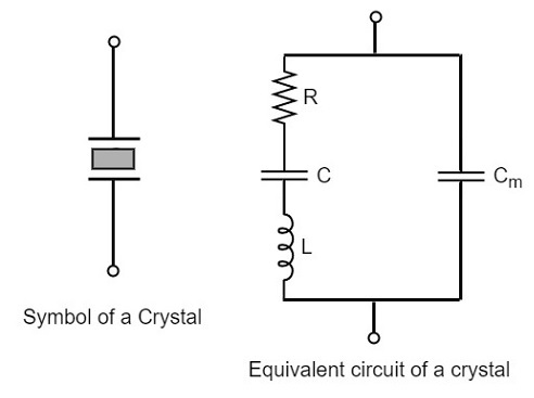
The above equivalent circuit consists of a series R-L-C circuit in parallel with a capacitance Cm. When the crystal mounted across the AC source is not vibrating, it is equivalent to the capacitance Cm. When the crystal vibrates, it acts like a tuned R-L-C circuit.
Frequency response
The frequency response of a crystal is as shown below. The graph shows the reactance (XL or XC) versus frequency (f). It is evident that the crystal has two closely spaced resonant frequencies.
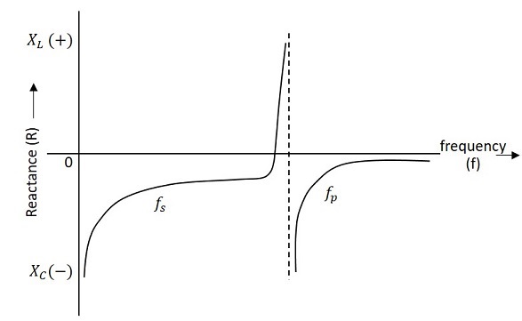
The first one is the series resonant frequency (fs), which occurs when reactance of the inductance (L) is equal to the reactance of the capacitance C. In that case, the impedance of the equivalent circuit is equal to the resistance R and the frequency of oscillation is given by the relation,
$$f = \frac{1}{2\pi \sqrt{L.C}}$$
The second one is the parallel resonant frequency (fp), which occurs when the reactance of R-L-C branch is equal to the reactance of capacitor Cm. At this frequency, the crystal offers a very high impedance to the external circuit and the frequency of oscillation is given by the relation.
$$f_p = \frac{1}{2\pi \sqrt{L.C_T}}$$
Where
$$C_T = \frac{C C_m}{(C + C_m)}$$
The value of Cm is usually very large as compared to C. Therefore, the value of CT is approximately equal to C and hence the series resonant frequency is approximately equal to the parallel resonant frequency (i.e., fs = fp).
Crystal Oscillator Circuit
A crystal oscillator circuit can be constructed in a number of ways like a Crystal controlled tuned collector oscillator, a Colpitts crystal oscillator, a Clap crystal oscillator etc. But the transistor pierce crystal oscillator is the most commonly used one. This is the circuit which is normally referred as a crystal oscillator circuit.
The following circuit diagram shows the arrangement of a transistor pierce crystal oscillator.
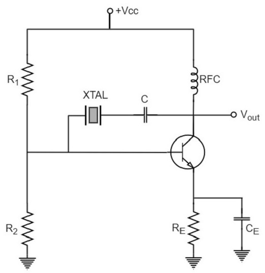
In this circuit, the crystal is connected as a series element in the feedback path from collector to the base. The resistors R1, R2 and RE provide a voltage-divider stabilized d.c. bias circuit. The capacitor CE provides a.c. bypass of the emitter resistor and RFC (radio frequency choke) coil provides for d.c. bias while decoupling any a.c. signal on the power lines from affecting the output signal. The coupling capacitor C has negligible impedance at the circuit operating frequency. But it blocks any d.c. between collector and base.
The circuit frequency of oscillation is set by the series resonant frequency of the crystal and its value is given by the relation,
$$f_o = \frac{1}{2\pi \sqrt{L.C}}$$
It may be noted that the changes in supply voltage, transistor device parameters etc. have no effect on the circuit operating frequency, which is held stabilized by the crystal.
Advantages
The advantages of crystal oscillator are as follows −
- They have a high order of frequency stability.
- The quality factor (Q) of the crystal is very high.
Disadvantages
The disadvantages of crystal oscillator are as follows −
- They are fragile and can be used in low power circuits.
- The frequency of oscillations cannot be changed appreciably.
Frequency Stability of an Oscillator
An Oscillator is expected to maintain its frequency for a longer duration without any variations, so as to have a smoother clear sinewave output for the circuit operation. Hence the term frequency stability really matters a lot, when it comes to oscillators, whether sinusoidal or non-sinusoidal.
The frequency stability of an oscillator is defined as the ability of the oscillator to maintain the required frequency constant over a long time interval as possible. Let us try to discuss the factors that affect this frequency stability.
Change in operating point
We have already come across the transistor parameters and learnt how important an operating point is. The stability of this operating point for the transistor being used in the circuit for amplification (BJT or FET), is of higher consideration.
The operating of the active device used is adjusted to be in the linear portion of its characteristics. This point is shifted due to temperature variations and hence the stability is affected.
Variation in temperature
The tank circuit in the oscillator circuit, contains various frequency determining components such as resistors, capacitors and inductors. All of their parameters are temperature dependent. Due to the change in temperature, their values get affected. This brings the change in frequency of the oscillator circuit.
Due to power supply
The variations in the supplied power will also affect the frequency. The power supply variations lead to the variations in Vcc. This will affect the frequency of the oscillations produced.
In order to avoid this, the regulated power supply system is implemented. This is in short called as RPS. The details of regulated power supply were clearly discussed in the power supply section of ELECTRONIC CIRCUITS tutorial.
Change in output load
The variations in output resistance or output load also affects the frequency of the oscillator. When a load is connected, the effective resistance of the tank circuit is changed. As a result, the Q-factor of LC tuned circuit is changed. This results a change in output frequency of oscillator.
Changes in inter-element capacitances
Inter-element capacitances are the capacitances that develop in PN junction materials such as diodes and transistors. These are developed due to the charge present in them during their operation.
The inter element capacitors undergo change due to various reasons as temperature, voltage etc. This problem can be solved by connecting swamping capacitor across offending inter-element capacitor.
Value of Q
The value of Q (Quality factor) must be high in oscillators. The value of Q in tuned oscillators determine the selectivity. As this Q is directly proportional to the frequency stability of a tuned circuit, the value of Q should be maintained high.
Frequency stability can be mathematically represented as,
$$S_w = d\theta/dw$$
Where dθ is the phase shift introduced for a small frequency change in nominal frequency fr. The circuit giving the larger value of (dθ/dw) has more stable oscillatory frequency.
