- Sinusoidal Oscillators - Home
- Oscillators - Introduction
- Oscillators - Basic Concepts
- Oscillators - Oscillator Circuit
- Tuned Circuit Oscillators
- Oscillators - Hartley Oscillator
- Oscillators - Colpitts Oscillator
- Oscillators - Clapp Oscillator
- Oscillators - Phase Shift Oscillators
- Wien Bridge Oscillator
- Oscillators - Crystal Oscillators
- Negative Resistance Oscillators
- Oscillators - Tunnel Diode Oscillator
- Sinusoidal Oscillators - Quick Guide
- Sinusoidal Oscillators - Resources
- Sinusoidal Oscillators - Discussion
Oscillator Circuit
An Oscillator circuit is a complete set of all the parts of circuit which helps to produce the oscillations. These oscillations should sustain and should be Undamped as just discussed before. Let us try to analyze a practical Oscillator circuit to have a better understanding on how an Oscillator circuit works.
Practical Oscillator Circuit
A Practical Oscillator circuit consists of a tank circuit, a transistor amplifier, and a feedback circuit. The following circuit diagram shows the arrangement of a practical oscillator.
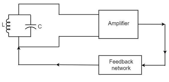
Let us now discuss the parts of this practical oscillator circuit.
Tank Circuit − The tank circuit consists of an inductance L connected in parallel with capacitor C. The values of these two components determine the frequency of the oscillator circuit and hence this is called as Frequency determining circuit.
Transistor Amplifier − The output of the tank circuit is connected to the amplifier circuit so that the oscillations produced by the tank circuit are amplified here. Hence the output of these oscillations are increased by the amplifier.
Feedback Circuit − The function of feedback circuit is to transfer a part of the output energy to LC circuit in proper phase. This feedback is positive in oscillators while negative in amplifiers.
Frequency Stability of an Oscillator
The frequency stability of an oscillator is a measure of its ability to maintain a constant frequency, over a long time interval. When operated over a longer period of time, the oscillator frequency may have a drift from the previously set value either by increasing or by decreasing.
The change in oscillator frequency may arise due to the following factors −
Operating point of the active device such as BJT or FET used should lie in the linear region of the amplifier. Its deviation will affect the oscillator frequency.
The temperature dependency of the performance of circuit components affect the oscillator frequency.
The changes in d.c. supply voltage applied to the active device, shift the oscillator frequency. This can be avoided if a regulated power supply is used.
A change in output load may cause a change in the Q-factor of the tank circuit, thereby causing a change in oscillator output frequency.
The presence of inter element capacitances and stray capacitances affect the oscillator output frequency and thus frequency stability.
The Barkhausen Criterion
With the knowledge we have till now, we understood that a practical oscillator circuit consists of a tank circuit, a transistor amplifier circuit and a feedback circuit. so, let us now try to brush up the concept of feedback amplifiers, to derive the gain of the feedback amplifiers.
Principle of Feedback Amplifier
A feedback amplifier generally consists of two parts. They are the amplifier and the feedback circuit. The feedback circuit usually consists of resistors. The concept of feedback amplifier can be understood from the following figure below.
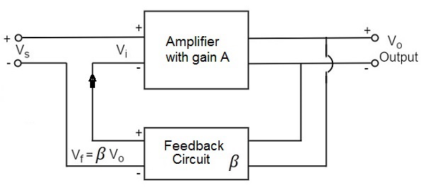
From the above figure, the gain of the amplifier is represented as A. The gain of the amplifier is the ratio of output voltage Vo to the input voltage Vi. The feedback network extracts a voltage Vf = β Vo from the output Vo of the amplifier.
This voltage is added for positive feedback and subtracted for negative feedback, from the signal voltage Vs.
So, for a positive feedback,
Vi = Vs + Vf = Vs + β Vo
The quantity β = Vf/Vo is called as feedback ratio or feedback fraction.
The output Vo must be equal to the input voltage (Vs + βVo) multiplied by the gain A of the amplifier.
Hence,
$$(V_s + \beta V_o)A = V_o$$
Or
$$AV_s + A\beta V_o = V_o$$
Or
$$AV_s = V_o(1 - A\beta)$$
Therefore
$$\frac{V_o}{V_s} = \frac{A}{1 - A\beta}$$
Let Af be the overall gain (gain with the feedback) of the amplifier. This is defined as the ratio of output voltage Vo to the applied signal voltage Vs, i.e.,
$$A_f = \frac{Output \: Voltage}{Input \: Signal \: Voltage} = \frac{V_o}{V_s}$$
Rrom the above two equations, we can understand that, the equation of gain of the feedback amplifier with positive feedback is given by
$$A_f = \frac{A}{1 - A\beta}$$
Where Aβ is the feedback factor or the loop gain.
If Aβ = 1, Af = ∞. Thus the gain becomes infinity, i.e., there is output without any input. In another words, the amplifier works as an Oscillator.
The condition Aβ = 1 is called as Barkhausen Criterion of oscillations. This is a very important factor to be always kept in mind, in the concept of Oscillators.
