- Sinusoidal Oscillators - Home
- Oscillators - Introduction
- Oscillators - Basic Concepts
- Oscillators - Oscillator Circuit
- Tuned Circuit Oscillators
- Oscillators - Hartley Oscillator
- Oscillators - Colpitts Oscillator
- Oscillators - Clapp Oscillator
- Oscillators - Phase Shift Oscillators
- Wien Bridge Oscillator
- Oscillators - Crystal Oscillators
- Negative Resistance Oscillators
- Oscillators - Tunnel Diode Oscillator
- Sinusoidal Oscillators - Quick Guide
- Sinusoidal Oscillators - Resources
- Sinusoidal Oscillators - Discussion
Phase Shift Oscillators
One of the important features of an oscillator is that the feedback energy applied should be in correct phase to the tank circuit. The oscillator circuits discussed so far has employed inductor (L) and capacitor (C) combination, in the tank circuit or frequency determining circuit.
We have observed that the LC combination in oscillators provide 180o phase shift and transistor in CE configuration provide 180 phase shift to make a total of 360o phase shift so that it would make a zero difference in phase.
Drawbacks of LC circuits
Though they have few applications, the LC circuits have few drawbacks such as
- Frequency instability
- Waveform is poor
- Cannot be used for low frequencies
- Inductors are bulky and expensive
We have another type of oscillator circuits, which are made by replacing the inductors with resistors. By doing so, the frequency stability is improved and a good quality waveform is obtained. These oscillators can also produce lower frequencies. As well, the circuit becomes neither bulky nor expensive.
All the drawbacks of LC oscillator circuits are thus eliminated in RC oscillator circuits. Hence the need for RC oscillator circuits arise. These are also called as Phaseshift Oscillators.
Principle of Phase-shift oscillators
We know that the output voltage of an RC circuit for a sinewave input leads the input voltage. The phase angle by which it leads is determined by the value of RC components used in the circuit. The following circuit diagram shows a single section of an RC network.
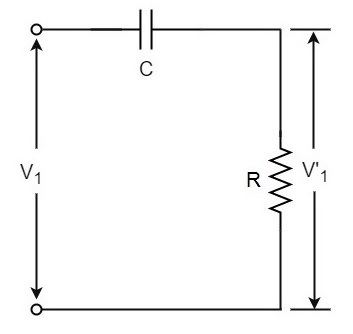
The output voltage V1 across the resistor R leads the input voltage applied input V1 by some phase angle ɸo. If R were reduced to zero, V1 will lead the V1 by 90o i.e., ɸo = 90o.
However, adjusting R to zero would be impracticable, because it would lead to no voltage across R. Therefore, in practice, R is varied to such a value that makes V1 to lead V1 by 60o. The following circuit diagram shows the three sections of the RC network.
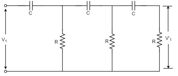
Each section produces a phase shift of 60o. Consequently, a total phase shift of 180o is produced, i.e., voltage V2 leads the voltage V1 by 180o.
Phase-shift Oscillator Circuit
The oscillator circuit that produces a sine wave using a phase-shift network is called as a Phase-shift oscillator circuit. The constructional details and operation of a phase-shift oscillator circuit are as given below.
Construction
The phase-shift oscillator circuit consists of a single transistor amplifier section and a RC phase-shift network. The phase shift network in this circuit, consists of three RC sections. At the resonant frequency fo, the phase shift in each RC section is 60o so that the total phase shift produced by RC network is 180o.
The following circuit diagram shows the arrangement of an RC phase-shift oscillator.
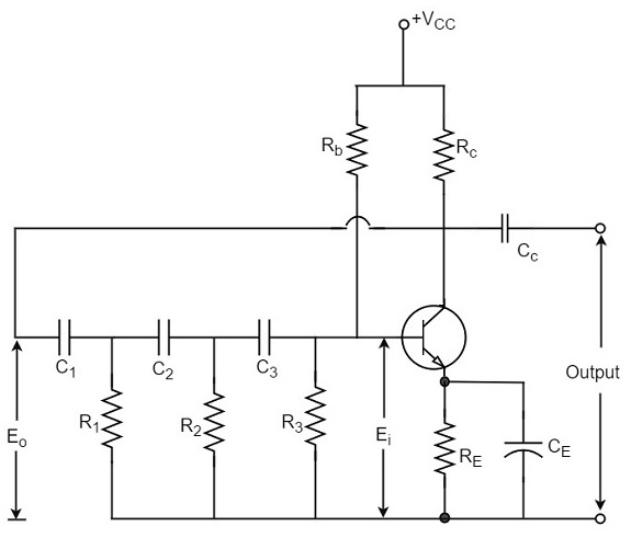
The frequency of oscillations is given by
$$f_o = \frac{1}{2\pi RC \sqrt{6}}$$
Where
$$R_1 = R_2 = R_3 = R$$
$$C_1 = C_2 = C_3 = C$$
Operation
The circuit when switched ON oscillates at the resonant frequency fo. The output Eo of the amplifier is fed back to RC feedback network. This network produces a phase shift of 180o and a voltage Ei appears at its output. This voltage is applied to the transistor amplifier.
The feedback applied will be
$$m = E_i/E_o$$
The feedback is in correct phase, whereas the transistor amplifier, which is in CE configuration, produces a 180o phase shift. The phase shift produced by network and the transistor add to form a phase shift around the entire loop which is 360o.
Advantages
The advantages of RC phase shift oscillator are as follows −
- It does not require transformers or inductors.
- It can be used to produce very low frequencies.
- The circuit provides good frequency stability.
Disadvantages
The disadvantages of RC phase shift oscillator are as follows −
- Starting the oscillations is difficult as the feedback is small.
- The output produced is small.
