- Sinusoidal Oscillators - Home
- Oscillators - Introduction
- Oscillators - Basic Concepts
- Oscillators - Oscillator Circuit
- Tuned Circuit Oscillators
- Oscillators - Hartley Oscillator
- Oscillators - Colpitts Oscillator
- Oscillators - Clapp Oscillator
- Oscillators - Phase Shift Oscillators
- Wien Bridge Oscillator
- Oscillators - Crystal Oscillators
- Negative Resistance Oscillators
- Oscillators - Tunnel Diode Oscillator
- Sinusoidal Oscillators - Quick Guide
- Sinusoidal Oscillators - Resources
- Sinusoidal Oscillators - Discussion
Hartley Oscillator
A very popular local oscillator circuit that is mostly used in radio receivers is the Hartley Oscillator circuit. The constructional details and operation of a Hartley oscillator are as discussed below.
Construction
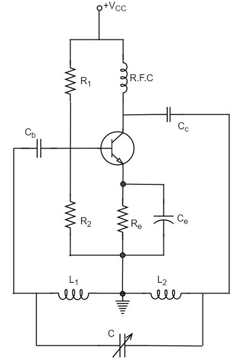
In the circuit diagram of a Hartley oscillator shown below, the resistors R1, R2 and Re provide necessary bias condition for the circuit. The capacitor Ce provides a.c. ground thereby providing any signal degeneration. This also provides temperature stabilization.
The capacitors Cc and Cb are employed to block d.c. and to provide an a.c. path. The radio frequency choke (R.F.C) offers very high impedance to high frequency currents which means it shorts for d.c. and opens for a.c. Hence it provides d.c. load for collector and keeps a.c. currents out of d.c. supply source
Tank Circuit
The frequency determining network is a parallel resonant circuit which consists of the inductors L1 and L2 along with a variable capacitor C. The junction of L1 and L2 are earthed. The coil L1 has its one end connected to base via Cc and the other to emitter via Ce. So, L2 is in the output circuit. Both the coils L1 and L2 are inductively coupled and together form an Auto-transformer.
The following circuit diagram shows the arrangement of a Hartley oscillator. The tank circuit is shunt fed in this circuit. It can also be a series-fed.
Operation
When the collector supply is given, a transient current is produced in the oscillatory or tank circuit. The oscillatory current in the tank circuit produces a.c. voltage across L1.
The auto-transformer made by the inductive coupling of L1 and L2 helps in determining the frequency and establishes the feedback. As the CE configured transistor provides 180o phase shift, another 180o phase shift is provided by the transformer, which makes 360o phase shift between the input and output voltages.
This makes the feedback positive which is essential for the condition of oscillations. When the loop gain |βA| of the amplifier is greater than one, oscillations are sustained in the circuit.
Frequency
The equation for frequency of Hartley oscillator is given as
$$f = \frac{1}{2 \pi \sqrt{L_T C}}$$
$$L_T = L_1 + L_2 + 2M$$
Here, LT is the total cumulatively coupled inductance; L1 and L2 represent inductances of 1st and 2nd coils; and M represents mutual inductance.
Mutual inductance is calculated when two windings are considered.
Advantages
The advantages of Hartley oscillator are
Instead of using a large transformer, a single coil can be used as an auto-transformer.
Frequency can be varied by employing either a variable capacitor or a variable inductor.
Less number of components are sufficient.
The amplitude of the output remains constant over a fixed frequency range.
Disadvantages
The disadvantages of Hartley oscillator are
- It cannot be a low frequency oscillator.
- Harmonic distortions are present.
Applications
The applications of Hartley oscillator are
- It is used to produce a sinewave of desired frequency.
- Mostly used as a local oscillator in radio receivers.
- It is also used as R.F. Oscillator.
