
Article Categories
- All Categories
-
 Data Structure
-
 Networking
-
 RDBMS
RDBMS
-
 Operating System
-
 Java
Java
-
 MS Excel
-
 iOS
iOS
-
 HTML
HTML
-
 CSS
CSS
-
 Android
-
 Python
-
 C Programming
-
 C++
C++
-
 C#
C#
-
 MongoDB
-
 MySQL
MySQL
-
 Javascript
-
 PHP
PHP
-
 Economics & Finance
Silicon Controlled Rectifier – Working Principle and Applications
An SCR is a three-terminal, three-junction, and four-layer semiconductor device that is used to perform switching functions in power circuits.
Sometimes the SCR is also called as Thyristor.
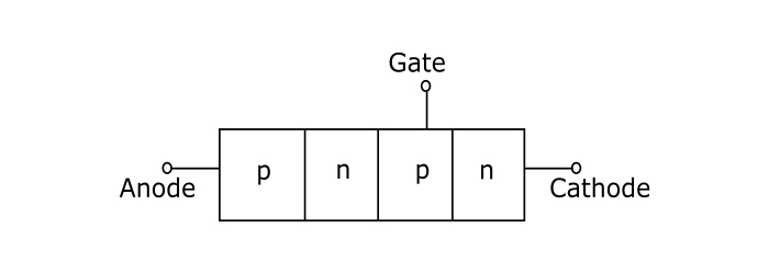
Constructional Details of SCR
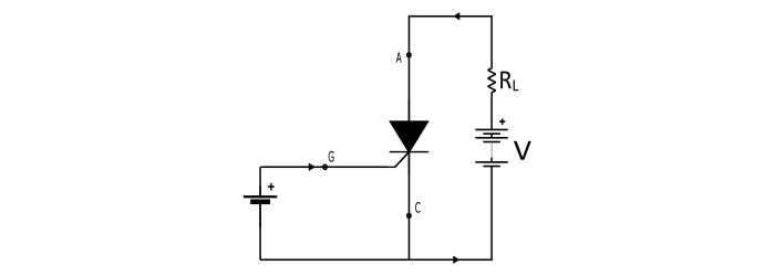
The SCR has three pn – junctions, and four layer of p and n type semiconductor joined alternatively to get pnpn device. The three terminals are taken – one from outer p – type layer called anode (A), second from the outer n – type layer called cathode (K) and the third from the internal p –type layer called gate (G).

Working of SCR
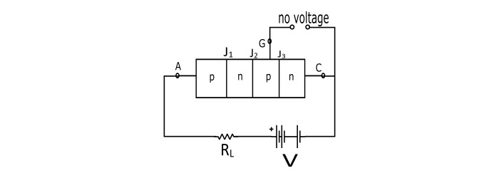
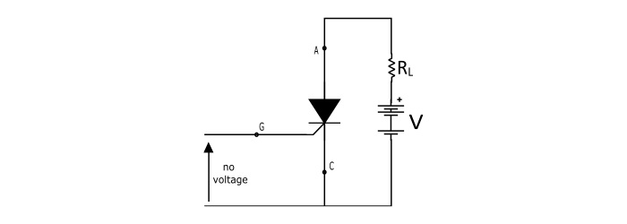
In a SCR, the load is connected in series with the anode. The anode is always kept positive with respect to cathode.
When Gate is Open Circuited
When no voltage applied to gate terminal, junction J2, is reverse biased and the junctions J1 and J3 are forward biased. Since one of the three junctions is reverse biased so there is no current can flow through the load, hence the SCR is OFF. However if the applied voltage is gradually increased, a stage is reached, when reverse biased junction (J2) breaks down. The SCR now, starts conducting and become ON. The value of applied voltage at which the reverse biased junction breaks down and the SCR becomes ON is known as Breakover Voltage.
When Gate is Positive with Respect to Cathode
The SCR can be turned ON at smaller applied voltage by the application of a small positive voltage at the gate terminal. When gate voltage is applied the junction J3 is forward biased and junction J2 is reverse biased. Thus, the electrons from n – type layer starts moving across the junction J3 toward p –type material and the holes from p –type material towards the n – type material. Due to the movement of holes and electrons across the junction J3 the gate current starts flowing. Because of gate current the anode current increases. The increased anode current makes the more electrons available at the junction J2. As a result of this process, in a small time, the junction J2 breaks down and the SCR is turn ON.
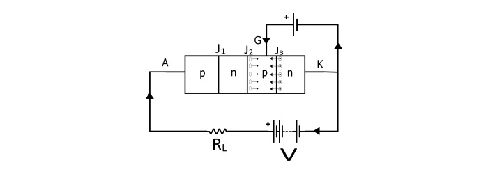
Even if the voltage at the gate terminal is removed, the SCR the anode current does not decrease. The SCR can only be turned off by reducing the applied voltage to zero.
Parameters of SCR
Break Over Voltage − It is the minimum value of the applied voltage at which the SCR is turned ON, provided the gate voltage is not applied. For commercially available SCRs the range of break over voltage is 50 V to 500 V.
Peak Reverse Voltage (PRV) − It is the maximum reverse voltage (i.e. cathode made positive with respect to the anode) that can be applied to the SCR without conducting in the reverse direction. The commercially available SCRs have PRV up to 2.5 kV.
Holding Current − With gate being open, it is the maximum value of anode current at which SCR is turned OFF from ON state.
Forward Current Rating − It is maximum value of the anode current that an SCR can pass through it without destruction.
Circuit Fusing Rating − It indicates the maximum forward surge current capability of the SCR. It is defined as the product of square of forward surge current and the time duration of the surge.
If the circuit fusing rating is exceeded in the SCR circuit, the device is destroyed by excessive power dissipation.
$$\mathrm{Circuit\:Fusing\:Rating=I^2t}$$
I–V Characteristics of SCR
It is the curve plotted between the anode – cathode voltage (V) and anode current (I) of the SCR at constant gate current.
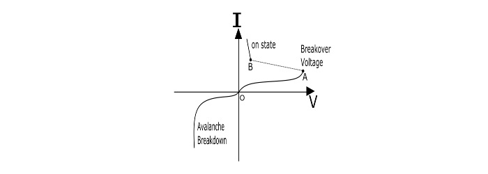
Forward Characteristics − When the anode is made positive with respect to the cathode, then the curve between V and I is called as forward characteristics of the SCR. If the supply voltage is increased from zero, a point is reached (Point A, the voltage is called breakover voltage) when the SCR starts conducting. Under this condition, the voltage across SCR decreases suddenly (shown by dotted line in the curve) and the most of the supply voltage appears across the load.
Reverse Characteristics − When anode is made negative with respect to the cathode, the curve plotted between V and I is called as reverse characteristics. If the reverse voltage is increased gradually, at first the anode current remains small (called leakage current) and at some reverse voltage, the avalanche breakdown occurs and the SCR starts conducting in the reverse direction (Shown by the curve in third quadrant). The maximum reverse voltage at which the SCR starts conducting in the reverse direction is called as Reverse Breakdown Voltage.
Applications of SCR
The SCR can be used in following application −
- Power Switching Circuit
- Controlled Rectifier
- AC power control circuits
- Speed control of DC shunt motor
- SCR Crowbar
- Computer logic circuits
- Timing Circuits
- Inverters
- Battery Charging Regulators
- Temperature control systems

77K+ Views
