
Article Categories
- All Categories
-
 Data Structure
-
 Networking
-
 RDBMS
RDBMS
-
 Operating System
-
 Java
Java
-
 MS Excel
-
 iOS
iOS
-
 HTML
HTML
-
 CSS
CSS
-
 Android
-
 Python
-
 C Programming
-
 C++
C++
-
 C#
C#
-
 MongoDB
-
 MySQL
MySQL
-
 Javascript
-
 PHP
PHP
-
 Economics & Finance
Real Time Clock (RTC) with Arduino
An RTC module keeps track of time once an initial time input is provided to it. This input can come from several sources (NTP, GPS, etc.). The RTC module usually comes with its own crystal oscillator, and even its own battery, so that the timekeeping continues, even if there is a power disturbance on the Arduino.
Circuit Diagram −
We will use the DS3231 module. It uses I2C for communication (SDA and SCL lines). The circuit diagram is shown below −
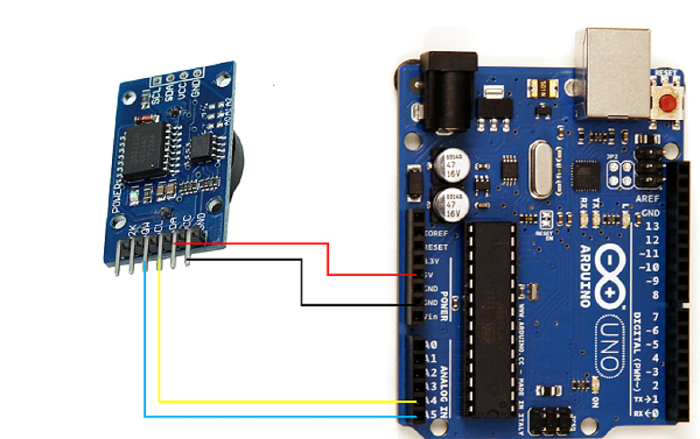
As you can see, the Vcc pin of DS3231 is connected to 5V, GND to GND, SDA to A4 (SDA) and SCL to A5 (SCL)
Required Libraries
You will need the ds3231 library.
A guide to installing libraries from GitHub is given here.
Code Walkthrough
The code will be kept simple. We will use the code given in a create.arduino project.
We begin with the inclusion of the Wire and ds3231 libraries −
#include <Wire.h>
#include <ds3231.h>
If you look at the source code of DS3231 library, they have defined a struct ts which contains various time fields (year, month, etc.). We will create a variable of this struct type.
struct ts t;
Within setup, we initialize Wire, DS3231 and set the initial time. Note that this initial time could come from GPS, NTP or other sources. Here we are setting it manually just for illustration.
void setup() {
   Serial.begin(9600);
   Wire.begin();
   DS3231_init(DS3231_CONTROL_INTCN);
   t.hour=12;
   t.min=30;
   t.sec=0;
   t.mday=25;
   t.mon=12;
   t.year=2019;

   DS3231_set(t);
}
The config used in DS3231_init (DS3231_CONTROL_INTCN) indicates interrupt control. The other options, defined in ds3231.h file are −
// control register bits
#define DS3231_CONTROL_A1IE          0x1       /* Alarm 2 Interrupt Enable */
#define DS3231_CONTROL_A2IE          0x2       /* Alarm 2 Interrupt Enable */
#define DS3231_CONTROL_INTCN         0x4       /* Interrupt Control */
#define DS3231_CONTROL_RS1           0x8       /* square-wave rate select 2 */
#define DS3231_CONTROL_RS2           0x10       /* square-wave rate select 2 */
#define DS3231_CONTROL_CONV          0x20       /* Convert Temperature */
#define DS3231_CONTROL_BBSQW         0x40       /* Battery-Backed Square-Wave Enable */
#define DS3231_CONTROL_EOSC          0x80       /* not Enable Oscillator, 0 equal on */
The meaning of these can be found in the Control register section of DS3231 datasheet. By setting the mode to DS3231_CONTROL_INTCN, we are in the interrupt output mode with alarms disabled. This will mean no square wave output or interrupt on the INT/SQW pin of DS3231 (because interrupts require alarm to be enabled). You need not worry much about that pin for the purpose of this tutorial. It is not used for usual timekeeping. You can read more about it in the datasheet.
Within the loop, we keep printing the time every second. You can observe on the Serial Monitor that the time increments in steps of 1 second as expected.
void loop() {
   DS3231_get(&t);
   Serial.print("Date : ");
   Serial.print(t.mday);
   Serial.print("/");
   Serial.print(t.mon);
   Serial.print("/");
   Serial.print(t.year);
   Serial.print("\t Hour : ");
   Serial.print(t.hour);
   Serial.print(":");
   Serial.print(t.min);
   Serial.print(".");
   Serial.println(t.sec);

   delay(1000);
} 
3K+ Views
