
Article Categories
- All Categories
-
 Data Structure
-
 Networking
-
 RDBMS
RDBMS
-
 Operating System
-
 Java
Java
-
 MS Excel
-
 iOS
iOS
-
 HTML
HTML
-
 CSS
CSS
-
 Android
-
 Python
-
 C Programming
-
 C++
C++
-
 C#
C#
-
 MongoDB
-
 MySQL
MySQL
-
 Javascript
-
 PHP
PHP
-
 Economics & Finance
Path Loss Definition, Overview and Formula
Usually, the wireless channel is noisy. We can’t have a noise-free communication. We often use the AWGN (Additive White Gaussian Noise) model for interpretation of the channel noise. Noise is assumed to get added to the signal and at the receiver; we have a signal that carries both the data and the noise. It is important that signal level at the receiver is reasonably above the noise floor so that the detector can faithfully detect and decode the signal data.
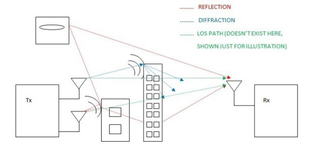
Apart from noise, losses in the atmosphere can also distort the transmitted signal. Some of the common losses taken into consideration during the design of wireless link budgets include atmospheric absorption loss, scattering loss (includes rain attenuation), reflection loss, diffraction loss and path loss. In this article, we will discuss the path loss and its effects on long distance wireless communications.
What is Path Loss?
Path loss (PL) refers to the loss or attenuation a propagating electromagnetic signal (or wave) encounters along its path from transmitter to the receiver.
As a result of path loss, the received signal power level is several orders below the transmitted power level. The received power level is dependent on factors such as transmission power, antenna gains, frequency of operation and the distance between the transmitter and the receiver. Like any other gain or attenuation, path loss is also expressed in decibel (dB). We can relate the received power level and the path loss but before that, let’s know the expression of path loss.
Definition of Path Loss Mathematically
The path loss is expressed mathematically as
$$PL(dB)=20log_{10}(\frac{4\pi\:d}{\lambda})\:---(1)$$
d is the distance between the transmitter and receiver and λ is the wavelength of the signal.
As said earlier, the received power level depends on the path loss. The expression for the received power at a distance‘d’ from the transmitter is expressed mathematically using Friis’ transmission equation as
$$P_{r}=P_{t}G_{t}G_{r}(\frac{\lambda}{4\pi\:d})^{2}\:---(2)$$
By definition, path loss is the ratio of the transmitted power to the received power. From the above equation, we can get the ratio of Pt and Pr.
$$\frac{P_{t}}{P_{r}}=\frac{1}{G_{t}G_{r}(\frac{\lambda}{4\pi\:d})^{2}}\:---(3)$$
How can Path Loss ratio be written in dB scale?
Now, expressing the ratio on dB scale, we have, (3), written as
$$10log_{10}(\frac{P_{t}}{P_{r}})=10log_{10}(\frac{1}{G_{t}G_{r}(\frac{\lambda}{4\pi\:d})^{2}})$$
$$PL(dB)=10log_{10}(\frac{P_{t}}{P_{r}})=-10log_{10}[{G_{t}G_{r}(\frac{\lambda}{4\pi\:d})^{2}}]$$
$$PL(dB)=-10log_{10}(G_{t}G_{r})-10log_{10}(\frac{\lambda}{4\pi\:d})^{2}$$
$$PL(dB)=-10log_{10}(G_{t}G_{r})+20log_{10}(\frac{4\pi\:d}{\lambda})\:---(4)$$
If the antenna gains are assumed to be unity, (4) reduces to give the expression of path loss −
$$PL(dB)=20log_{10}(\frac{4\pi\:d}{\lambda})\:---(5)$$
In the original form, path loss is given by
$$PL(dB)=10log_{10}(\frac{4\pi\:d}{\lambda})^{2}\:---(6)$$
We can observe that PL is a function of square of the signal frequency and the distance between the transmitter and receiver.
The received power level depends on the path loss. More the path loss, less is the available received power. We aim to reduce the path loss to maximize the power level available at the receiver.
How can received power Pr be expressed in dB?
Expressing (2) in dB, we have,
$$P_{r}(dB)=P_{t}(dB)+G_{t}(dB)+G_{r}(dB)+20log_{10}(\frac{\lambda}{4\pi\:d})\:---(7)$$
Re-writing (7), we have,
$$P_{r}(dB)=P_{t}(dB)+G_{t}(dB)+G_{r}(dB)-20log_{10}(\frac{4\pi\:d}{\lambda})\:---(7)$$
This can also be written as
$$P_{r}(dB)=P_{t}(dB)+G_{t}(dB)+G_{r}(dB)-PL(dB)$$
Thus,
$$PL(dB)=P_{t}(dB)+G_{t}(dB)+G_{r}(dB)-P_{r}(dB)\:---(8)$$
From (8), we can observe that as the transmission power is increased, the path loss is reduced. Deploying high gain antennas is another way to reduce the path loss. We can tune these parameters to the requirements of the application.
This path loss model (also termed free space path loss model) becomes more relatable to line-of-sight or near line-of-sight communications such as microwave communications and satellite communications. On the other side, commercial AM radio broadcasting doesn’t essentially require line-of-sight communications. WLAN based communications also fall into this category.

20K+ Views
