- NGN - Home
- NGN - Pulse Code Modulation
- NGN - Multiplexing
- NGN - Frame Structure
- NGN - Higher Order Multiplexing
- Plesiochronous Digital Hierarchy
- NGN - Synchronous Digital Hierarchy
- NGN - WDM Technology
- Micro Electro Mechanical Systems
- NGN - Varieties Of WDM
NGN - WDM Technology
WDM is a technology that enables various optical signals to be transmitted by a single fiber. Its principle is essentially the same as frequency-division multiplexing (FDM). That is, several signals are transmitted using different carriers, occupying non-overlapping parts of a frequency spectrum. In case of WDM, the spectrum band used is in the region of 1300 or 1550 nm, which are two wavelength windows at which optical fibers have very low signal loss.
Initially, each window was used to transmit a single digital signal. With the advance of optical components such as distributed feedback (DFB) lasers, erbium-doped fiber amplifiers (EDFAs), and photo-detectors, it was soon realized that each transmitting window could in fact be used by several optical signals, each occupying a small traction of the total wavelength window available.
In fact, the number of optical signals multiplexed within a window is limited only by the precision of these components. With current technology, over 100 optical channels can be multiplexed into a single fiber. The technology was then named dense WDM (DWDM).
DWDM's main advantage is its potential to cost effectively increase the optical fiber bandwidth many folds. The large network of fibers in existence around the world can suddenly have their capacity multiplied manifold, without the need to long new fibers, an expensive process. Obviously, new DWDM equipment must be connected to these fibers. Also, optical regenerators might be needed.
The number and frequency of wavelengths to be used is being standardized by the ITU (T). The wavelength set used is important not only for interoperability, but also to avoid destructive interference between optical signals.
The following Table gives nominal, central frequencies based on the 50 GHz, minimum channel spacing anchored to 193.10 THz reference. Note that the value of C (velocity of light) is taken equal to 2.99792458 x 10⁸ m/sec. for converting between frequency and wavelength.
The ITU-T Grid (within C-band), ITU (T) Rec. G.692
| Nominal central frequencies (THz) for spacing of 50 GHz | Nominal central frequencies (THz) for spacing of 100 GHz | Nominal central wavelengths (Nm) |
|---|---|---|
| 196.10 | 196.10 | 1528.77 |
| 196.05 | 1529.16 | |
| 196.00 | 196.00 | 1529.55 |
| 195.95 | 1529.94 | |
| 195.90 | 195.90 | 1530.33 |
| 195.85 | 1530.72 | |
| 195.80 | 195.80 | 1531.12 |
| 195.75 | 1531.51 | |
| 195.70 | 195.70 | 1531.90 |
| 195.65 | 1532.29 | |
| 195.60 | 195.60 | 1532.68 |
| 195.55 | 1533.07 | |
| 195.50 | 195.50 | 1533.47 |
| 195.45 | 1533.86 | |
| 195.40 | 195.40 | 1534.25 |
| 195.35 | 1534.64 | |
| 195.30 | 195.30 | 1535.04 |
| 195.25 | 1535.43 | |
| 195.20 | 195.20 | 1535.82 |
| 195.15 | 1536.22 | |
| 195.10 | 195.10 | 1536.61 |
| 195.05 | 1537.00 | |
| 195.00 | 195.00 | 1537.40 |
| 194.95 | 1537.79 | |
| 194.90 | 194.90 | 1538.19 |
| 194.85 | 1538.58 | |
| 194.80 | 194.80 | 1538.98 |
| 194.75 | 1539.37 | |
| 194.70 | 194.70 | 1539.77 |
| 194.65 | 1540.16 | |
| 194.60 | 194.60 | 1540.56 |
| 194.55 | 1540.95 | |
| 194.50 | 194.50 | 1541.35 |
| 194.45 | 1541.75 | |
| 194.40 | 194.40 | 1542.14 |
| 194.35 | 1542.54 | |
| 194.30 | 194.30 | 1542.94 |
| 194.25 | 1543.33 | |
| 194.20 | 194.20 | 1543.73 |
| 194.15 | 1544.13 | |
| 194.10 | 194.10 | 1544.53 |
| 194.05 | 1544.92 | |
| 194.00 | 194.00 | 1545.32 |
| 193.95 | 1545.72 | |
| 193.90 | 193.90 | 1546.12 |
| 193.85 | 1546.52 | |
| 193.80 | 193.80 | 1546.92 |
| 193.75 | 1547.32 | |
| 193.70 | 193.70 | 1547.72 |
| 193.65 | 1548.11 | |
| 193.60 | 193.60 | 1548.51 |
| 193.55 | 1548.91 | |
| 193.50 | 193.50 | 1549.32 |
| 193.45 | 1549.72 | |
| 193.40 | 193.40 | 1550.12 |
| 193.35 | 1550.52 | |
| 193.30 | 193.30 | 1550.92 |
| 193.25 | 1551.32 | |
| 193.20 | 193.20 | 1551.72 |
| 193.15 | 1552.12 | |
| 193.10 | 193.10 | 1552.52 |
| 193.05 | 1552.93 | |
| 193.00 | 193.00 | 1533.33 |
| 192.95 | 1553.73 | |
| 192.90 | 192.90 | 1554.13 |
| 192.85 | 1554.54 | |
| 192.80 | 192.80 | 1554.94 |
| 192.75 | 1555.34 | |
| 192.70 | 192.70 | 1555.75 |
| 192.65 | 1556.15 | |
| 192.60 | 192.60 | 1556.55 |
| 192.55 | 1556.96 | |
| 192.50 | 192.50 | 1557.36 |
| 192.45 | 1557.77 | |
| 192.40 | 192.40 | 1558.17 |
| 192.35 | 1558.58 | |
| 192.30 | 192.30 | 1558.98 |
| 192.25 | 1559.39 | |
| 192.20 | 192.20 | 1559.79 |
| 192.15 | 1560.20 | |
| 192.10 | 192.10 | 1560.61 |
DWDM Within The Network
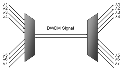
A typical SDH network will have two fibers on each side of every node, one to transmit to its neighbor on and one to receive from its neighbor on.
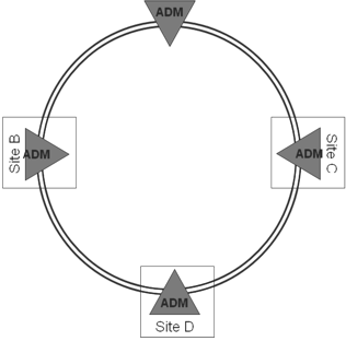
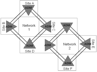
While having two fibers between a site doesnt sound too bad, in practice there will probably be many systems running between sites, even though they dont form part of the same network.
With just the two networks shown above, four fibers are now required between sites C & D, and laying between sites is extremely expensive. This is where DWDM networks come into play.
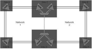
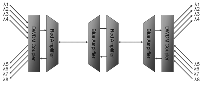
Using a DWDM system, the amount of fibers required between sites C & D is reduced to a single fiber. Modern DWDM equipment can multiplex up to 160 channels, representing a massive saving in fiber investment. Because DWDM equipment works only with the physical signal, it does not affect the SDH layer of the network at all. The SDH signal is not terminated or interrupted, as far as the SDH network is concerned. There is still a direct connection between the sites.
DWDM networks are protocol independent. They transport wavelengths of light and do not operate at the protocol layer.
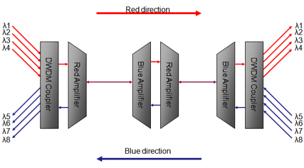
DWDM systems can save network operators large amounts of money when laying fiber, even more over the long distances. Using optical amplifiers, it is possible to transmit a DWDM signal to long distances.
An amplifier receives a multi-wavelength DWDM signal and simply amplifies it to reach the next site.
An op-amp will amplify either the red or blue lambdas, if it is amplifying the red lambdas, it will drop out the received blue channels and vice versa. To amplify in both directions, one of both types of amplifier is required.
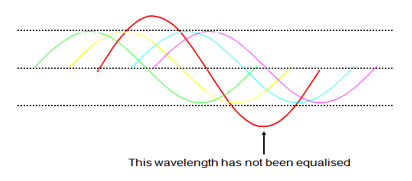
For the DWDM system to operate in a satisfactory way, the incoming wavelengths to the optical amplifier should be equalized.
This involves setting all the incoming optical sources to the DWDM system to similar optical power levels. Wavelengths that have not been equalized may show errors when carrying traffic.
Some manufacturers DWDM equipment assists field technicians by measuring the optical powers of the incoming channels and recommending, which channels require power adjustment.
Equalizing the wavelengths can be done in a several ways; A variable optical attenuator can be fitted between the fiber management frame and the DWDM coupler an engineer can adjust the signal at the DWDM coupler side.
Alternatively, the source equipment may have variable output optical transmitters, this allows an engineer to adjust the optical power through software at the source equipment.
Some DWDM couplers have attenuators built in for every received channel, an engineer can adjust every channel at the DWDM access point.
When multiple frequencies of light travel through a fiber, a condition known as four wave mixing may occur. New wavelengths of light are generated within the fiber at wavelengths/frequencies determined by the frequency of the original wavelengths. The frequency of the new wavelengths is given by f123 = f1 + f2 - f3.
The presence of the wavelengths can adversely affect the optical signal to noise ratio within the fiber, and affect the BER of traffic within a wavelength.
WDM COMPONENTS
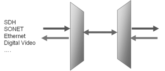
WDM components are based on various optics principles. The Figure given below depicts a single WDM link. DFB lasers are used as transmitters, one for each wavelength. An optical multiplexer combines these signals into the transmission fiber. Optical amplifiers are used to pump the optical signal power up, to compensate for system losses.
On the receiver side, optical de-multiplexers separate each wavelength, to be delivered to optical receivers at the end of the optical link. Optical signals are added to the system by the optical ADMs (OADMs).
These optical devices are equivalent to the digital ADMs, grooming and splitting optical signals along the transmission path. OADMs are usually made of arrayed-waveguide gratings (AWG), although other optical technologies, such as fiber bragg gratings, have also been used.
A key WDM component is the optical switch. This device is capable of switching optical signals from a given input port to a given output port. It is the equivalent of an electronic crossbar. Optical switches enable optical networks to be constructed, so a given optical signal can be routed towards its appropriate destination.
Another important optical component is the wavelength converter. A wavelength converter is a device that converts an optical signal coming at a given wavelength into another signal on a different wavelength, maintaining the same digital content. This capability is important for WDM networks because it provides more flexibility in routing optical signals across the network.
OPTICAL TRANSPORT NETWORKS
WDM networks are constructed by connecting wavelength cross connect (WXC) nodes in a certain topology of choice. WXCs are realized by wavelength multiplexers and demultiplexers, switches, and wavelength converters.
The following Figure depicts a generic WXC node architecture.
Optical signals, multiplexed in the same fiber, arrive at an optical demultiplexer. The signal is decomposed into its several wavelength carriers, and sent to a bank of optical switches. The optical switches route the several wavelength signals into a bank of output.
Multiplexers, where the signals are multiplexed and injected into the outgoing fibers for transmission. Wavelength converters may be used between the optical switch and the output multiplexers in order to provide more routing flexibility. WXCs have been researched for a number of years. The difficulties with WXCs are crosstalk and extinction ratio.
A Wavelength Cross-Connect Node
Optical transport networks (OTNs) are WDM networks providing transport services via light paths. A light path is a high-bandwidth pipe carrying data at up to several gigabits per second. The speed of the light path is determined by the technology of the optical components (lasers, optical amplifiers, etc.). Speeds on the order of STM-16 (2488.32 Mbps) and STM-64 (9953.28 Mbps) are currently achievable.
An OTN is composed of WXC nodes, plus a management system, which controls the set-up and teardown of light paths through supervisory functions such as monitoring of optical devices (amplifier, receivers), fault recovery, and so on. The set up and teardown of light paths are to be executed over a large time scale such as hours or even days, given that each of them provides backbone bandwidth capacity.
There is a lot of flexibility in how OTNs are deployed, depending on the transport services to be provided. One of the reasons for this flexibility is that most optical components are transparent to signal encoding. Only at the boundary of the optical layer, where the optical signal needs to be converted back to the electronic domain, does the encoding matter.
Thus, transparent optical services to support various legacy electronic network technologies, such as SDH, ATM, IP and frame relay, running on top of the optical layer, is a likely scenario in the future.
The optical layer is further divided into three sublayers −
The optical channel layer network, which interfaces with OTN clients, providing optical channels (OChs).
The optical multiplex layer network, which multiplexes various channels into a single optical signal.
The optical transmission section layer network, which provides the transmission of the optical signal across the fiber.
OTN FRAME FORMAT
Similar to the use of a SDH frame, access to the OCh is expected to be through an OC frame, which is currently defined. The basic frame size corresponds to STM-16 speed or 2488.32 Mbps, which constitutes the basic OCh signal. The following Figure depicts a possible OCh frame format.

An Optical Channel Frame
The leftmost region of the frame (shown in the Figure given below) is reserved for overhead bytes. These bytes are to be used for OAM&P functions, similar to the overhead bytes of the SDH frame, discussed earlier.
However, additional functions are likely to be supported, such as the provision of dark fibers (reservation of a wavelength between two end points for a single user) and wavelength-based APS. The rightmost region of the frame is reserved for a forward error correction (FEC) scheme to be exercised on all payload data. An FEC over an optical transmission layer increases the maximum span length, and reduces the number of repeaters. A Reed-Solomon code can be used.
Several OChs are to be multiplexed together in the optical domain, to form the optical multiplexer signal (OMS). This parallels to the multiplexing of several STM-1 frames into an STM-N SDH frame format. Multiple OChs can be multiplexed to form OMS.
The optical client signal is placed within the OCh payload signal. Client signal is not constrained by the OCh frame format. Instead, the client signal is required to be only a constant bit rate digital signal. Its format is also irrelevant to the optical layer.
WDM RINGS
Conceptually, a WDM ring is not much different from a SDH ring. WXCs are interconnected in a ring topology, similar to SDH ADMs in a SDH-ring. The major architectural difference between a SDH ring and a WDM ring is rooted in the WXC capabilities of wavelength switching and conversion.
These features can be used for instance, to provide levels of protection with no parallel in SDH technology. In other words, wavelength or light path protection can be provided, in addition to path and line protection.
Optical APS protocols are as complex as SDH APSs. Protection can be provided either at the OCh level or the optical multiplex section/optical transmission section level. Some extra protection capabilities can be implemented with no parallel in SDH rings. For instance, a failed light path (e.g. a laser failure) can be fixed by converting an optical signal from a given wavelength into a different one, avoiding the rerouting of the signal.
This is equivalent to span switching in SDH, with the difference that even two fiber WDM rings can provide such capability for OCh protection. In the OMS layer, however, span protection will require four fiber rings, as in SDH. These extra features will undoubtedly introduce extra complexity in the optical-layer APS protocols.
Once the WDM ring is up, light paths need to be established in accordance with the traffic pattern to be supported.
MESH WDM NETWORKS
Mesh WDM networks are constructed with the same optical components as WDM rings. However, the protocols used in mesh networks are different from those used in rings. For instance, protection in mesh networks is a more complex proposition as is the problem of routing and wavelength assignment in WDM mesh networks.
Mesh networks are likely to be as backbone infrastructures connecting WDM rings. Some of these connections are expected to be optical, avoiding optical/electronic bottlenecks and providing transparency. Others will require the conversion of the optical signal into the electronic domain for monitoring management, and perhaps billing purposes. The following Figure depicts a WDM network.

Infrastructure − In this figure, three following topology layers are shown −
- Access Network
- Regional Network
- Backbone Network
WDM Network Infrastructure
Both SDH rings and passive optical networks (PONs) as access networks are included. They are generally based on a bus, or star topology and medium access control (MAC) protocol is used to coordinate transmissions among the users. No routing functionality is provided in such networks.
These architectures are practical for networks supporting at most a few hundred users over short distances. Although PONs are less expensive networks than WDM rings, due to the lack of active components and features such as wavelength routing, the lasers necessary at the PON sources make the first generation of such equipment still more expensive than SDH rings. This favors the SDH solution at the access network level, at least in the near future.
Backbone networks contain active optical components, hence providing functions such as wavelength conversion and routing. The backbone networks will have to somehow interface with legacy transport technologies, such as ATM, IP, PSTN, and SDH.
The overall scenario is depicted in the following Figure. Several types of interface involved in the figure.
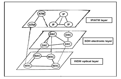
Overlaying a WDM Transport Network carrying ATM/IP Traffic.
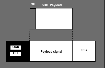
SDH Frame Encapsulation
The OCh frame must be defined so that SDH frame encapsulation can be easily done. The entire STM-16xc, for instance has to be carried as an OCh payload. If a basic STM-16 optical channel is used, it might not be possible to encapsulate SDH-16xc into STM-16 optical channel, due to the OCh overhead bytes.
The OCh frame format is currently being defined. The following Figure exemplifies SDH frame encapsulation into OCh frame.
SDH Interfaces to WDM
WDM equipment with physical SDH interfaces will deliver optical signals to SDH devices. These interfaces must be for backward compatibility with SDH technology. Therefore, the SDH device need not be aware of the WDM technology used to transport its signal (e.g. the device can belong to a BLSR/4 ring).
In this case, the WXC will drop and add into the optical medium the wavelength originally used in the SDH ring. This way, WDM and SDH layers are completely decoupled, which is necessary for WDM interoperability with SDH legacy equipment.
This puts extra constraints on the selection of wavelengths in the optical layer, since the last-hop wavelength, the one interfacing with the SDH device, must be the same one used by SDH device to terminate the optical path, if wavelength conversion is not provided within SDH device.
A WDM Link
| Technology | Detection | Restoration | Details | |
|---|---|---|---|---|
| WDM | WDM-OMS/OCH | 1-10ms | 10-30ms | Ring/P-P |
| SDH | SDH | 0.1ms | 50ms | Ring |
| APS 1+1 | 0.1ms | 50ms | P-P | |
| ATM | FDDI | 0.1ms | 10ms | Ring |
| STM | 0.1ms | 100ms | ||
| ATM PV-C/P 1+1 | 0.1ms | 10msxN | Standby N=#hops | |
| ATM PNNI SPV-C/P, SV-C/P | 40s | 1-10s | ||
| IP | Border Gateway Protocol | 180ms | 10-100s | |
| Interior Gateway Routing Protocol and E-OSPF | 40s | 1-10s | ||
| Intermediate System | 40s | 1-10s | ||
| Routing Internet Protocol | 180s | 100s |
As per the Table shown above, although restoration is faster in WDM than the SDH technology, failure detection in WDM is slower. Safer overlay of WDM/SDH protection mechanisms calls for a faster WDM protection scheme. Alternatively, SDH APSs could be artificially slowed down if SDH clients can afford the performance degradation incurred by such procedures.
Unnecessary failure recovery at higher layers may cause route instability and traffic congestion; hence, it should be avoided at all costs. Fault persistence checks can be used at higher layers to avoid early reaction to faults at lower layers.
A failure recovery at the OMS sublayer can replace recovery procedures of several instances of the SDH signals being served by optical layer. Thus, a potentially large number of SDH clients are spared from starting failure recovery procedures at their layers. Therefore, a single failure recovery at the optical OMS sublayer can spare hundreds.
Evolution towards an All-Optical Transport Network
Evolution towards an all-optical WDM network is likely to occur gradually. First, WXC devices will be connected to existing fibers. Some extra components might be necessary in the optical link, such as EDFAs, in order to make legacy fiber links suitable to WDM technology. WXCs will interface with legacy equipment, such as SDH and fiber distributed data interface (FDDI).
A plus of an all-optical transparent transport network is that the transferring of SDH functions into either the layer above (IP/ATM) or below (WDM) SDH is likely to happen, bringing savings in terms of network upgradability and maintenance. Such layer re-organization could affect transport networks, assume that real-time traffic, including voice, is packetized (IP/ATM). This could lead to the extinction of VCs' SDH signals.
A key issue then would be how to most efficiently pack packets into SDH, or even directly into OCh frames. Whatever new encapsulation method emerges, back compatibility with IP/PPP/HDLC and ATM encapsulation is a must.
