- NGN - Home
- NGN - Pulse Code Modulation
- NGN - Multiplexing
- NGN - Frame Structure
- NGN - Higher Order Multiplexing
- Plesiochronous Digital Hierarchy
- NGN - Synchronous Digital Hierarchy
- NGN - WDM Technology
- Micro Electro Mechanical Systems
- NGN - Varieties Of WDM
NGN - Synchronous Digital Hierarchy
SDH Networks replaced PDH and had several key advantages.
G.707, G.708, and G.709 ITU recommendations provide basis for global networking.
Networks benefit from traffic resilience to minimize traffic loss in the event of fiber break of equipment failure.
Built in monitoring technology allows remote configuration and troubleshooting of network.
Flexible technology allows for tributary access at any level.
Future proof technology allows for faster bit rates as technology advances.
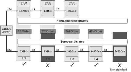
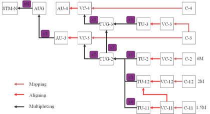
Whereas European PDH networks could not interface with US networks, SDH networks can carry both types. This slide shows how the different PDH networks compare and which signals can be carried across the SDH network.
SDH Network Topologies
Line System

A lone system is system to the PDH network topology. Traffic is added and dropped only at the end points of the network. Terminal nodes are used at the end of the network for adding and dropping the traffic.
Within any SDH network, it is possible to use a node known as a regenerator. This node receives the high order SDH signal and retransmits it. No lower order traffic access is possible from a regenerator and they are only used to cover long distances between sites where the distance means that the received power would be too low to carry traffic.
Ring System
A ring system consists of several add/drop muxes (ADMs) connected in a ring configuration. Traffic can be accessed at any ADM around the ring and it is also possible for traffic to be dropped at several nodes for the broadcast purposes.
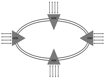
The ring network also has the benefit of offering traffic resilience, if there is a fibre break traffic I not lost. Network resilience is discussed in further detail later.
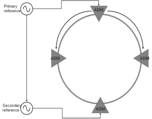
SDH Network Synchronisation
While PDH networks were not centrally synchronized, SDH networks are (hence the name synchronous digital hierarchy). Somewhere on the operators network will be a primary reference source. This source is distributed around the network either over the SDH network or over a separate synchronization network.
Each node can switch to backup sources if the main source becomes unavailable. Various quality levels are defined and the node will switch the next best quality source it can find. In cases where the node uses the incoming line timing the S1 byte in the MS overhead is used to denote the quality of the source.
The lowest quality source available to a node is generally its internal oscillator, in a case where a node switches to its own internal clock source, this should be remedied as soon as possible as the node may start to generate errors over time.
It is important that the synchronization strategy for a network is planned carefully, if all the nodes in a network try to synchronize off its neighbor on the same side you will get an effect called a timing loop, as shown above. This network will quickly start to generate errors as each node tries to synchronize off each other.
SDH Hierarchy
The following diagram shows how the payload is constructed, and it isnt as scary as it looks at first. The next couple of slides will explain how the SDH signal is constructed from the lower level payloads.
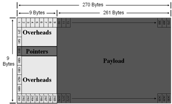
STM-1 Frame
The frame is made up of rows of 9 overheads and 261 payload bytes.
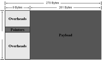
The frame is transmitted row by row as illustrated below. The 9 overhead bytes in a row are transmitted, followed by the 261 bytes of payload, the next row is then transmitted in similar fashion until the whole frame has been transmitted. The whole frame is transmitted in 125 micro seconds.
STM-1 Overheads
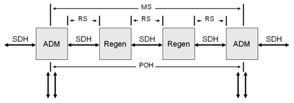
The first 3 rows of the overhead are called the repeater section overheads. The 4th row form the AU pointers, and the last 5 rows hold the multiplex section overheads.
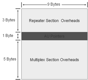
To explain the different types of overheads consider a system where the payload is passed through several intermediate regenerators before reaching the ADM that it is being added/dropped from.
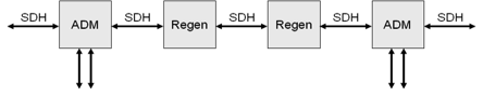
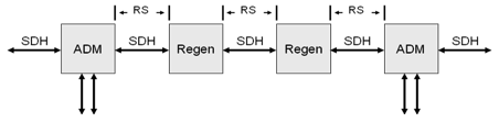
The repeater section overheads are used for communications and monitoring between any two neighboring nodes.
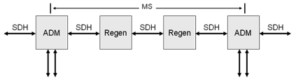
The multiplex section overheads are used for communications and monitoring between two nodes that have add/drop facilities such as ADMs.
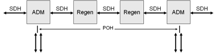
At a lower level, there are also path overheads that are added at a tributary level, these will be discussed in further detail later.
The monitoring of different overhead alarms makes it easier to pinpoint trouble on the network. An RS alarm indicate a problem on the HO SDH side between two nodes, while if investigating an MS alarm you can rule out problems at the regenerator nodes.
SDH Path Trace
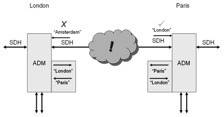
The path trace can be very useful in pinpointing interconnection problems between nodes. There may be various physical interconnections such as splices and patches within optical frames between two nodes. Each node is configured by the network operator to send a unique string that identifies it.
Each node is also configured with the string that it should receive from its neighboring node.
If the path trace that is received by the node matches the one that they are expecting, then everything is OK.
If the received path trace does not match the trace that the node is expecting, then this indicates a problem with the connection between the nodes.
SDH Management
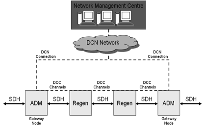
The DCC channels contained within the section overheads allow for easy management of the SDH network. A network management system connected to a node on the network can communicate with other nodes on the network using the DCC channels. The node that is connected to the DCN network is known as the gateway node, for resilience purposes there is usually more than one gateway node on the network.
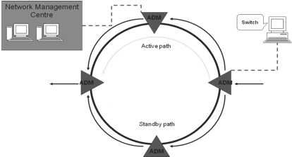
SDH Network Resilience
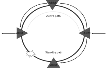
In a ring configuration traffic is sent both routes around the ring from the originating ADM (Add/Drop Multiplexer). At any ADM where the signal is not dropped it simply passes through. Although traffic passes round the ring over both routes, but only one route is used to extract traffic from at the receiving ADM, this route is the active route or path. The other route is known as the standby route or path.
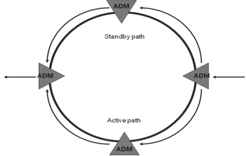
If there is a fiber break on the active path, the receiving ADM will switch using the alternative signal as the active path. This allows fast and automatic restoration of traffic flow to customers. When the fiber break is repaired, the ring does not automatically switch back as this would cause a further traffic hit, but will use this as the standby path in case of future failure on the new active path. The MUX that loses traffic will use the K bytes to signal the protection switch back to the originating MUX.
Manual ring switches can also be performed either from the network management center or from local terminals operated by engineers.