- NGN - Home
- NGN - Pulse Code Modulation
- NGN - Multiplexing
- NGN - Frame Structure
- NGN - Higher Order Multiplexing
- Plesiochronous Digital Hierarchy
- NGN - Synchronous Digital Hierarchy
- NGN - WDM Technology
- Micro Electro Mechanical Systems
- NGN - Varieties Of WDM
NGN - Quick Guide
NGN - Pulse Code Modulation
The advent of high-speed voice and data communications has brought about the need for a fast medium for transporting the information. Digital circuits or links have evolved from the need to transmit voice or data in digital form.
The conversion from analogue to digital form follows a four-stage processes (see the following Figure) and will be detailed in the following sections.

Sampling
Voice frequencies take the form of an analogue signal i.e. sine wave (see the following Figure). This signal has to be converted into a binary form for it to be carried over a digital medium. The first stage of this conversion is to convert the audio signal into a Pulse Amplitude Modulation(PAM) signal. This process is generically known as sampling.

The sampling process must gather sufficient information from the incoming voice frequencies to enable a copy of the original signal to be made. Voice frequencies are normally in the range of 300Hz to 3400Hz, typically known as the commercial speech band.
To obtain a sample, a sampling frequency is applied to the original voice frequency. The sampling frequency is determined by the Nyquist Sampling Theorem, which dictates that the frequency of sampling should be at least twice the highest frequency component.
This ensures that a sample is taken a minimum of once in each half cycle, thus, eliminating the possibility of sampling at zero points of the cycle, which would have no amplitude. This results into the sampling frequency being a minimum of 6.8 KHz.
The European standard samples an incoming signal at 8 KHZ, ensuring a sample, is taken every 125micro seconds or 1/8000th of a second (see the following Figure).

Quantization
The amplitude of each sample would ideally be assigned a binary code (1s or 0s), but as there can be an infinite number of amplitudes; therefore, there need to be an infinite number of binary codes available. This would be impractical, so another process has to be employed, which is known as quantizing.
Quantizing compares the PAM signal against a quantizing scale, which has a finite number of discrete levels. The quantizing scale splits into 256 quantizing levels, of which, 128 are positive levels and 128 are negative levels.
The quantization stage involves allocating a unique 8 bit binary code appropriate to the quantizing interval into which the amplitude of the PAM signal falls (see the following Figure).

This comprises of 1 polarity bit with the remaining 7 bits used to identify the quantization level (as shown in the above figure).
The first bit as seen before is the polarity bit, the next three bits for the segment code, giving eight segment codes, and the remaining four bits for the quantization level, giving sixteen quantization levels.
Companding
The quantizing process itself leads to a phenomenon known as quantization distortion. This occurs when the sampled signal amplitude falls between the quantization levels. The signal is always rounded up to the nearest whole level. This difference between the sampled level and the quantizing level is quantizing distortion.
The rate of change of the amplitude of a signal varies at different parts of the cycle. This happens most at high frequencies as the amplitude of the signal changes faster than at the low frequencies. To overcome this, the first segment code has the quantization levels close together. The next segment code is then double the height of the previous and so on. This process is known as companding, as it compresses larger signals and expands smaller signals.

In Europe they use the A-law of companding, compared to North America and Japan who use the law.
As quantization distortion is equivalent to noise, companding improves the signal to noise ratio on low amplitude signals, and produces an acceptable signal to noise ratio over the complete range of amplitudes.
Encoding
In order for the binary information to be transmitted over a digital path, the information has to be modified into a suitable line code. The encoding technique employed in Europe is known as High Density Bipolar 3 (HDB3).
HDB3 is derived from a line code called AMI or Alternate Mark Inversion. Within AMI encoding, there are 3 values used: no signal to represent a binary 0, and a positive or negative signal that is used alternately to represent a binary 1.
One problem associated with AMI encoding occurs when a long string of zeros are transmitted. This can cause phase lock loop problems at the distant end receiver.
HDB3 works in a similar way to AMI, but incorporates an extra encoding step that replaces any string of four zeros by three zeros followed by a 'violation bit. This violation is of the same polarity of the previous transition (see the following Figure).

As can be seen in the example, 000V replaces the first string of four zeros. However, using this type of encoding could lead to a mean D.C. level being introduced into the signal, as a long string of zeros could be present, all being encoded in the same way. To avoid this, the encoding of each successive four zeros is changed to B00V, by using a 'Bipolar violation' bit that alternates in polarity.
From this, it can be assumed that with HDB3 encoding, the maximum number of zeros without a transition is three. This encoding technique is often referred as the modulation format.
NGN - Multiplexing
Multiplexing
So far, we have been concentrating only on one voice channel. Now, we need to combine a number of these channels into a single transmission path, a process known as multiplexing. Multiplexing is a process employed whereupon several channels can be combined, in order for them to be transmitted over a single transmission path. The process commonly in use in telephony is known as Time Division Multiplexing (TDM).
As we have seen before, sampling for one channel takes place every 125 micro seconds. This makes it possible to sample other channels during this period. In Europe, the time span is divided into 32 time periods, known as timeslots. These 32 timeslots can then be grouped together to form a frame (see the following figure).
Consequently, the time duration of a frame can be considered as 125micro seconds. It can now also be assumed that as each timeslot consists of 8 data bits, and is repeated 8000 times a channel rate of 64000 bits per second or 64Kbits is attainable. With this information it is now possible to determine the total number of data bits transmitted over the single path, known as the system bit rate. This is calculated using the following formula −
System bit rate = Sampling frequency x Number of timeslots x Bits per timeslot = 8000 x 32 x 8, = 2048000 bits/sec, = 2.048Mbits
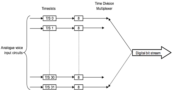
Of the 32 channels available, 30 are used for speech transmission, and the remaining 2 timeslots are used for alignment and signaling. The following section will explain the function of all the timeslots.
NGN - Frame Structure
Timeslot 1 to 15 and 17 to 31
These 30 timeslots are available for the transmission of the digitized analogue signal in 8-bit form, with a bandwidth of 64 kbit/s (e.g. the customers data).
Timeslot 0
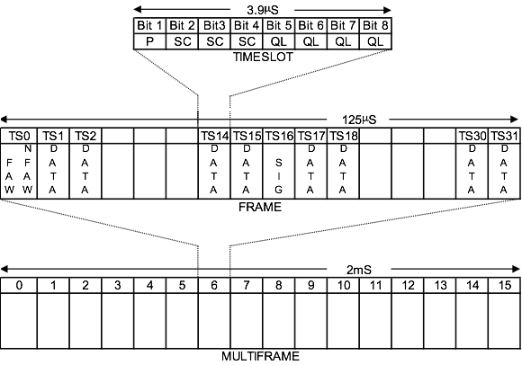
The European recommended system defines that the Timeslot 0 of each frame is used for synchronization, also known as frame alignment (see the following Figure). This ensures that the timeslots in each frame are aligned between the transmitting station and the receiving station.

The frame alignment word (FAW) is carried in data bits 2 to 8 of each even frame, while the odd frames carry a not frame alignment word (NFAW) in data bit 2 (see the following Figure).

An error check is also available in timeslot 0, using a cyclic redundancy check (CRC) to verify the frame alignment, which is carried in data bit 1 of all frames. There is also the facility of reporting Far End Alarms, which is indicated by a binary 1 being inserted in data bit 3 of all the odd frames. The remaining data bits 4 to 8 of the odd frames can be utilized for national alarms and network management.
Timeslot 16
Timeslot 16 has 8 data bits available, and by using a variable code of 4 data bits, signaling can be performed for 2 voice channels in each frame.
TTherefore it can be seen that 15 frames are required to complete the signaling for all the voice channels (see the following Figure).

As there are now multiple frames being carried in a logical order, there has to be a device for aligning these. This is achieved by using the frame prior to the frames containing signaling information, known as Frame 0.
Timeslot 16 in Frame 0 contains a multi-frame alignment word (MFAW), using data bits 1 to 4, and are used to indicate the start of a multi-frame, which are checked at the receiving station (see the following Figure).

Data bit 6 can be used to indicate distant multi-frame alignment loss (DLMFA). As can be seen, a multi-frame consists of all the frames required to complete all speech and signaling operations, i.e. 16 frames, and is known as a multi-frame (see the following Figure).
The duration of a multi-frame can be calculated using the following −
Duration of multiframe = Number of frames x duration of frame
= 16 x 125micro seconds
= 2000micro seconds
= 2 milli seconds
The remaining channels are all usable for voice or data transmission, and are known as timeslots 1 to 15 and 17 to 31, and equate to channels numbered 1 to 30.
FAW = Frame Alignment Word
MFAW = Multiframe Alignment Word
DATA = 8 bit data words
SIG = CAS signalling timeslot
NGN - Higher Order Multiplexing
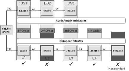
The Plesiochronous Digital Hierarchy (PDH) has been developed in stages from the basic 30-channel PCM (PCM-30) system.
As can be seen in the following Figure, there are three different hierarchical systems available, each supporting different line rates and multiplexing rates. The higher aggregate rates can therefore be achieved by grouping together the lower rates through the use of multiplexers.

The higher bit rate links also require additional bits for framing and control. For example, an 8.4 Mbits signal comprises of 4 2.048 Mbits = 8.192 Mbits, with the remaining 256 Kbits being used for framing and control.
The European and North American hierarchy systems are often referred by the letter E for European and T for North American, with the hierarchy levels being numbered consecutively. These hierarchy levels can be compared in the following Figure −
| Hierarchy Level | Bit Rate (Mbits) | Voice Channels | |
|---|---|---|---|
| North America | T1 | 1.544 | 24 |
| T2 | 6.312 | 96 | |
| T3 | 44.736 | 672 | |
| T4 | 274.176 | 4032 | |
| European | E1 | 2.048 | 30 |
| E2 | 8.448 | 120 | |
| E3 | 34.368 | 480 | |
| E4 | 139.264 | 1920 | |
| Not Defined | 565.148 | 7680 |
These bit rates are often abbreviated to 1.5 meg, 3 meg, 6 meg, 44 meg, 274 meg and 2 meg, 8 meg, 34 meg, 140 meg, and 565 meg respectively.
As the legacy of PDH is so prominent in the telecommunications industry, it became necessary to accommodate these line rates in any new technology to be introduced, therefore many of the PDH line rates are supported by the Synchronous Digital Hierarchy (SDH). The only exception to this is the omission of the 8.4 Mbits level, which no longer has any practical meaning and is not supported by SDH.
In the basic 2 Mbits system, the data is byte interleaved, whereby each 8-bit timeslot is sent one after the other. In the case of the higher hierarchy levels, the data streams are multiplexed together bit-by-bit. A disadvantage of this system is that the bit rate of each tributary signal can vary from the nominal value due to each multiplexer having their own independent clock supplies. These clock deviations are dependent on the line rate and can be compensated for by using justification techniques within the bandwidth remaining after the multiplexing stage. The line rate also dictates the line code used for transmission as can be seen below −
| Bit Rate(Mbits) | Number of 64Kbit Channels | Permitted clock deviation (ppm) | Interface code | Preferred medium/line code | ||
|---|---|---|---|---|---|---|
| Balanced | Coaxial | Optical Fibre | ||||
| 2.048 | 30 | ±50 | AMI | HDB3 | ||
| 8.448 | 120 | ±30 | HDB3 | HDB3 | HDB3 | |
| 34.368 | 480 | ±20 | HDB3 | HDB3 | 4B3T 2B1Q |
5B6B |
| 139.264 | 1920 | ±15 | CMI | 4B3T | 5B6B | |
NGN - Plesiochronous Digital Hierarchy
Properties of PDH
Plesiochronous − Almost Synchronous
Multiplexing of 2 Mbit/s signals into higher order multiplexed signals.
Laying cable between switch sites is very expensive.
Increasing traffic capacity of a cable by increasing bit rate.
4 lower order signals multiplexed into single higher order signal at each level.
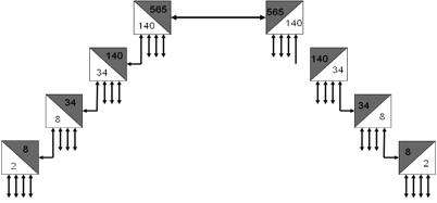
PDH technology allow successive multiplexing of a signal from 2 M 8 M, from 8 M 34 M, from 34 M 140 M and finally 140 M 565 M systems.
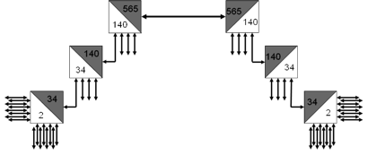
There also existed jump or skip muxes that would allow multiplexing of 16 2 M signals into a 34 M signal without the intermediate 8 M level.
PDH Limitations
Synchronisation − The data is transmitted at regular intervals. With timing derived from the transmitters oscillator, the data is sampled at the same rate as it is being transmitted.
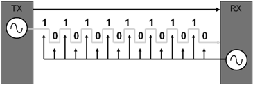
The data is transmitted at regular intervals. With timing derived from the transmitters oscillator, the data is sampled at a slower rate than the transmitter. One of the disadvantages of PDH was that each element was synchronized independently. For data to be received correctly, the sampling rate at the receiver end must be the same as the transmission rate at the transmitter end.
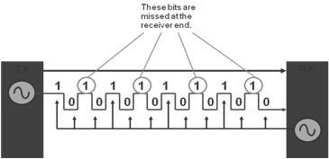
The data is transmitted at regular intervals. With timing derived from the transmitters oscillator, the data is sampled at a faster rate than the transmitter. If the oscillator at the receiver end was running slower than that at the transmitter end the receiver would miss some of the bits of the transmitted signal.
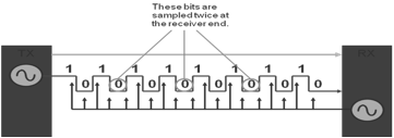
Or, if the receiver clock was running faster than that of the transmitter, the receiver would sample some of the bits twice.
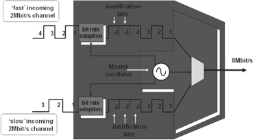
Justification bits are added to lower order signals so that they can be multiplexed at a single rate. The equipment oscillator is used as a timing source for the bit rate adaption process on the lower order and also on the multiplex proceed. Justification bits are discarded at the received end when the signals are de-multiplexed.
Because of the synchronization methods that were used, it was impossible to de-multiplex from a high order signal to the lowest order tributary signal in one piece of equipment. It was necessary to de-multiplex at all levels to access the signal that was being dropped at a site and then re-multiplex all the other channels back up to the higher rate. This meant that there had to be a lot of equipment on the site to accomplish this. This is known as the PDH Mux Mountain. All this equipment took up a lot of space on the site and also increased the need for spares to be held on sites.
Lack of resilience in PDH networks meant that if a fiber break occurred, the traffic would be lost. PDH network management simply reports alarms to NOC operators. No diagnosis or remedial tools are available to NOC staff. A maintenance engineer need to be sent on the site with a minimum amount of information. Each network element requires a connection to the DCN network as no facilities exist to carry management information across the PDH network.
Lack of standards for interconnection meant that it was not possible to interconnect equipment from multiple vendors. Equipment could operate on different wavelength, use different bit-rates, or proprietary optical interfaces.
NGN - Synchronous Digital Hierarchy
SDH Networks replaced PDH and had several key advantages.
G.707, G.708, and G.709 ITU recommendations provide basis for global networking.
Networks benefit from traffic resilience to minimize traffic loss in the event of fiber break of equipment failure.
Built in monitoring technology allows remote configuration and troubleshooting of network.
Flexible technology allows for tributary access at any level.
Future proof technology allows for faster bit rates as technology advances.
Whereas European PDH networks could not interface with US networks, SDH networks can carry both types. This slide shows how the different PDH networks compare and which signals can be carried across the SDH network.
SDH Network Topologies
Line System

A lone system is system to the PDH network topology. Traffic is added and dropped only at the end points of the network. Terminal nodes are used at the end of the network for adding and dropping the traffic.
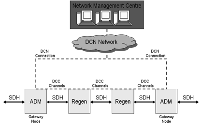
Within any SDH network, it is possible to use a node known as a regenerator. This node receives the high order SDH signal and retransmits it. No lower order traffic access is possible from a regenerator and they are only used to cover long distances between sites where the distance means that the received power would be too low to carry traffic.
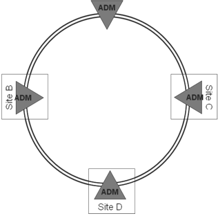
Ring System
A ring system consists of several add/drop muxes (ADMs) connected in a ring configuration. Traffic can be accessed at any ADM around the ring and it is also possible for traffic to be dropped at several nodes for the broadcast purposes.
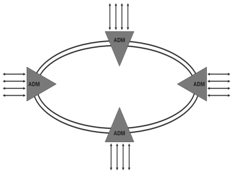
The ring network also has the benefit of offering traffic resilience, if there is a fibre break traffic I not lost. Network resilience is discussed in further detail later.
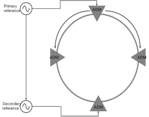
SDH Network Synchronisation
While PDH networks were not centrally synchronized, SDH networks are (hence the name synchronous digital hierarchy). Somewhere on the operators network will be a primary reference source. This source is distributed around the network either over the SDH network or over a separate synchronization network.
Each node can switch to backup sources if the main source becomes unavailable. Various quality levels are defined and the node will switch the next best quality source it can find. In cases where the node uses the incoming line timing the S1 byte in the MS overhead is used to denote the quality of the source.
The lowest quality source available to a node is generally its internal oscillator, in a case where a node switches to its own internal clock source, this should be remedied as soon as possible as the node may start to generate errors over time.
It is important that the synchronization strategy for a network is planned carefully, if all the nodes in a network try to synchronize off its neighbor on the same side you will get an effect called a timing loop, as shown above. This network will quickly start to generate errors as each node tries to synchronize off each other.
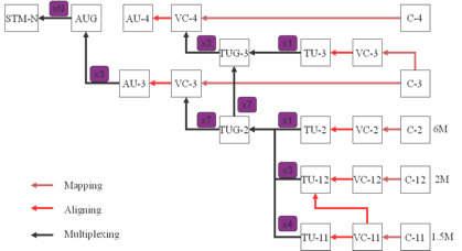
SDH Hierarchy
The following diagram shows how the payload is constructed, and it isnt as scary as it looks at first. The next couple of slides will explain how the SDH signal is constructed from the lower level payloads.
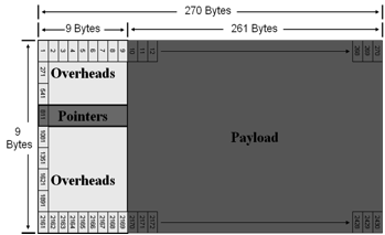
STM-1 Frame
The frame is made up of rows of 9 overheads and 261 payload bytes.
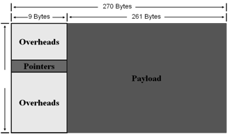
The frame is transmitted row by row as illustrated below. The 9 overhead bytes in a row are transmitted, followed by the 261 bytes of payload, the next row is then transmitted in similar fashion until the whole frame has been transmitted. The whole frame is transmitted in 125 micro seconds.
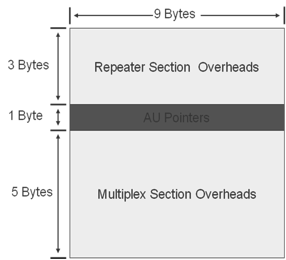
STM-1 Overheads
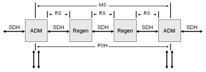
The first 3 rows of the overhead are called the repeater section overheads. The 4th row form the AU pointers, and the last 5 rows hold the multiplex section overheads.
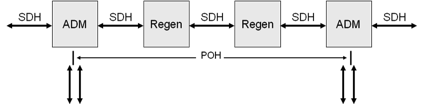
To explain the different types of overheads consider a system where the payload is passed through several intermediate regenerators before reaching the ADM that it is being added/dropped from.

The repeater section overheads are used for communications and monitoring between any two neighboring nodes.
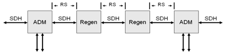
The multiplex section overheads are used for communications and monitoring between two nodes that have add/drop facilities such as ADMs.
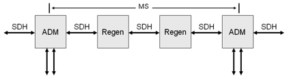
At a lower level, there are also path overheads that are added at a tributary level, these will be discussed in further detail later.
The monitoring of different overhead alarms makes it easier to pinpoint trouble on the network. An RS alarm indicate a problem on the HO SDH side between two nodes, while if investigating an MS alarm you can rule out problems at the regenerator nodes.
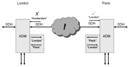
SDH Path Trace
The path trace can be very useful in pinpointing interconnection problems between nodes. There may be various physical interconnections such as splices and patches within optical frames between two nodes. Each node is configured by the network operator to send a unique string that identifies it.
Each node is also configured with the string that it should receive from its neighboring node.
If the path trace that is received by the node matches the one that they are expecting, then everything is OK.
If the received path trace does not match the trace that the node is expecting, then this indicates a problem with the connection between the nodes.
SDH Management
The DCC channels contained within the section overheads allow for easy management of the SDH network. A network management system connected to a node on the network can communicate with other nodes on the network using the DCC channels. The node that is connected to the DCN network is known as the gateway node, for resilience purposes there is usually more than one gateway node on the network.
SDH Network Resilience
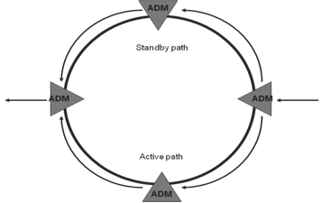
In a ring configuration traffic is sent both routes around the ring from the originating ADM (Add/Drop Multiplexer). At any ADM where the signal is not dropped it simply passes through. Although traffic passes round the ring over both routes, but only one route is used to extract traffic from at the receiving ADM, this route is the active route or path. The other route is known as the standby route or path.
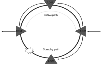
If there is a fiber break on the active path, the receiving ADM will switch using the alternative signal as the active path. This allows fast and automatic restoration of traffic flow to customers. When the fiber break is repaired, the ring does not automatically switch back as this would cause a further traffic hit, but will use this as the standby path in case of future failure on the new active path. The MUX that loses traffic will use the K bytes to signal the protection switch back to the originating MUX.
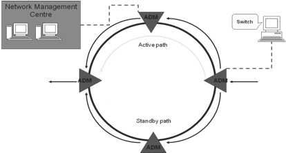
Manual ring switches can also be performed either from the network management center or from local terminals operated by engineers.
NGN - WDM Technology
WDM is a technology that enables various optical signals to be transmitted by a single fiber. Its principle is essentially the same as frequency-division multiplexing (FDM). That is, several signals are transmitted using different carriers, occupying non-overlapping parts of a frequency spectrum. In case of WDM, the spectrum band used is in the region of 1300 or 1550 nm, which are two wavelength windows at which optical fibers have very low signal loss.
Initially, each window was used to transmit a single digital signal. With the advance of optical components such as distributed feedback (DFB) lasers, erbium-doped fiber amplifiers (EDFAs), and photo-detectors, it was soon realized that each transmitting window could in fact be used by several optical signals, each occupying a small traction of the total wavelength window available.
In fact, the number of optical signals multiplexed within a window is limited only by the precision of these components. With current technology, over 100 optical channels can be multiplexed into a single fiber. The technology was then named dense WDM (DWDM).
DWDM's main advantage is its potential to cost effectively increase the optical fiber bandwidth many folds. The large network of fibers in existence around the world can suddenly have their capacity multiplied manifold, without the need to long new fibers, an expensive process. Obviously, new DWDM equipment must be connected to these fibers. Also, optical regenerators might be needed.
The number and frequency of wavelengths to be used is being standardized by the ITU (T). The wavelength set used is important not only for interoperability, but also to avoid destructive interference between optical signals.
The following Table gives nominal, central frequencies based on the 50 GHz, minimum channel spacing anchored to 193.10 THz reference. Note that the value of C (velocity of light) is taken equal to 2.99792458 x 10⁸ m/sec. for converting between frequency and wavelength.
The ITU-T Grid (within C-band), ITU (T) Rec. G.692
| Nominal central frequencies (THz) for spacing of 50 GHz | Nominal central frequencies (THz) for spacing of 100 GHz | Nominal central wavelengths (Nm) |
|---|---|---|
| 196.10 | 196.10 | 1528.77 |
| 196.05 | 1529.16 | |
| 196.00 | 196.00 | 1529.55 |
| 195.95 | 1529.94 | |
| 195.90 | 195.90 | 1530.33 |
| 195.85 | 1530.72 | |
| 195.80 | 195.80 | 1531.12 |
| 195.75 | 1531.51 | |
| 195.70 | 195.70 | 1531.90 |
| 195.65 | 1532.29 | |
| 195.60 | 195.60 | 1532.68 |
| 195.55 | 1533.07 | |
| 195.50 | 195.50 | 1533.47 |
| 195.45 | 1533.86 | |
| 195.40 | 195.40 | 1534.25 |
| 195.35 | 1534.64 | |
| 195.30 | 195.30 | 1535.04 |
| 195.25 | 1535.43 | |
| 195.20 | 195.20 | 1535.82 |
| 195.15 | 1536.22 | |
| 195.10 | 195.10 | 1536.61 |
| 195.05 | 1537.00 | |
| 195.00 | 195.00 | 1537.40 |
| 194.95 | 1537.79 | |
| 194.90 | 194.90 | 1538.19 |
| 194.85 | 1538.58 | |
| 194.80 | 194.80 | 1538.98 |
| 194.75 | 1539.37 | |
| 194.70 | 194.70 | 1539.77 |
| 194.65 | 1540.16 | |
| 194.60 | 194.60 | 1540.56 |
| 194.55 | 1540.95 | |
| 194.50 | 194.50 | 1541.35 |
| 194.45 | 1541.75 | |
| 194.40 | 194.40 | 1542.14 |
| 194.35 | 1542.54 | |
| 194.30 | 194.30 | 1542.94 |
| 194.25 | 1543.33 | |
| 194.20 | 194.20 | 1543.73 |
| 194.15 | 1544.13 | |
| 194.10 | 194.10 | 1544.53 |
| 194.05 | 1544.92 | |
| 194.00 | 194.00 | 1545.32 |
| 193.95 | 1545.72 | |
| 193.90 | 193.90 | 1546.12 |
| 193.85 | 1546.52 | |
| 193.80 | 193.80 | 1546.92 |
| 193.75 | 1547.32 | |
| 193.70 | 193.70 | 1547.72 |
| 193.65 | 1548.11 | |
| 193.60 | 193.60 | 1548.51 |
| 193.55 | 1548.91 | |
| 193.50 | 193.50 | 1549.32 |
| 193.45 | 1549.72 | |
| 193.40 | 193.40 | 1550.12 |
| 193.35 | 1550.52 | |
| 193.30 | 193.30 | 1550.92 |
| 193.25 | 1551.32 | |
| 193.20 | 193.20 | 1551.72 |
| 193.15 | 1552.12 | |
| 193.10 | 193.10 | 1552.52 |
| 193.05 | 1552.93 | |
| 193.00 | 193.00 | 1533.33 |
| 192.95 | 1553.73 | |
| 192.90 | 192.90 | 1554.13 |
| 192.85 | 1554.54 | |
| 192.80 | 192.80 | 1554.94 |
| 192.75 | 1555.34 | |
| 192.70 | 192.70 | 1555.75 |
| 192.65 | 1556.15 | |
| 192.60 | 192.60 | 1556.55 |
| 192.55 | 1556.96 | |
| 192.50 | 192.50 | 1557.36 |
| 192.45 | 1557.77 | |
| 192.40 | 192.40 | 1558.17 |
| 192.35 | 1558.58 | |
| 192.30 | 192.30 | 1558.98 |
| 192.25 | 1559.39 | |
| 192.20 | 192.20 | 1559.79 |
| 192.15 | 1560.20 | |
| 192.10 | 192.10 | 1560.61 |
DWDM Within The Network
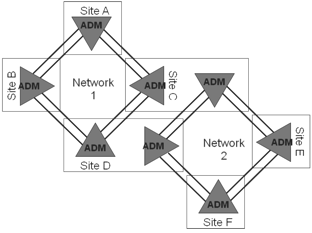
A typical SDH network will have two fibers on each side of every node, one to transmit to its neighbor on and one to receive from its neighbor on.
While having two fibers between a site doesnt sound too bad, in practice there will probably be many systems running between sites, even though they dont form part of the same network.
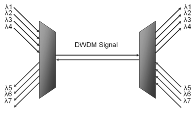
With just the two networks shown above, four fibers are now required between sites C & D, and laying between sites is extremely expensive. This is where DWDM networks come into play.
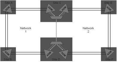
Using a DWDM system, the amount of fibers required between sites C & D is reduced to a single fiber. Modern DWDM equipment can multiplex up to 160 channels, representing a massive saving in fiber investment. Because DWDM equipment works only with the physical signal, it does not affect the SDH layer of the network at all. The SDH signal is not terminated or interrupted, as far as the SDH network is concerned. There is still a direct connection between the sites.
DWDM networks are protocol independent. They transport wavelengths of light and do not operate at the protocol layer.
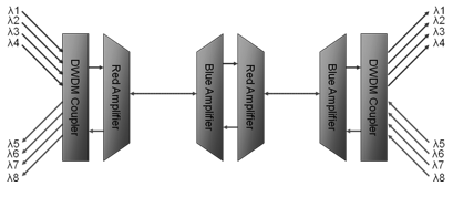
DWDM systems can save network operators large amounts of money when laying fiber, even more over the long distances. Using optical amplifiers, it is possible to transmit a DWDM signal to long distances.
An amplifier receives a multi-wavelength DWDM signal and simply amplifies it to reach the next site.
An op-amp will amplify either the red or blue lambdas, if it is amplifying the red lambdas, it will drop out the received blue channels and vice versa. To amplify in both directions, one of both types of amplifier is required.
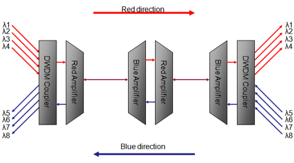
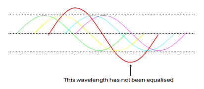
For the DWDM system to operate in a satisfactory way, the incoming wavelengths to the optical amplifier should be equalized.
This involves setting all the incoming optical sources to the DWDM system to similar optical power levels. Wavelengths that have not been equalized may show errors when carrying traffic.
Some manufacturers DWDM equipment assists field technicians by measuring the optical powers of the incoming channels and recommending, which channels require power adjustment.
Equalizing the wavelengths can be done in a several ways; A variable optical attenuator can be fitted between the fiber management frame and the DWDM coupler an engineer can adjust the signal at the DWDM coupler side.
Alternatively, the source equipment may have variable output optical transmitters, this allows an engineer to adjust the optical power through software at the source equipment.
Some DWDM couplers have attenuators built in for every received channel, an engineer can adjust every channel at the DWDM access point.
When multiple frequencies of light travel through a fiber, a condition known as four wave mixing may occur. New wavelengths of light are generated within the fiber at wavelengths/frequencies determined by the frequency of the original wavelengths. The frequency of the new wavelengths is given by f123 = f1 + f2 - f3.
The presence of the wavelengths can adversely affect the optical signal to noise ratio within the fiber, and affect the BER of traffic within a wavelength.
WDM COMPONENTS
WDM components are based on various optics principles. The Figure given below depicts a single WDM link. DFB lasers are used as transmitters, one for each wavelength. An optical multiplexer combines these signals into the transmission fiber. Optical amplifiers are used to pump the optical signal power up, to compensate for system losses.
On the receiver side, optical de-multiplexers separate each wavelength, to be delivered to optical receivers at the end of the optical link. Optical signals are added to the system by the optical ADMs (OADMs).
These optical devices are equivalent to the digital ADMs, grooming and splitting optical signals along the transmission path. OADMs are usually made of arrayed-waveguide gratings (AWG), although other optical technologies, such as fiber bragg gratings, have also been used.
A key WDM component is the optical switch. This device is capable of switching optical signals from a given input port to a given output port. It is the equivalent of an electronic crossbar. Optical switches enable optical networks to be constructed, so a given optical signal can be routed towards its appropriate destination.
Another important optical component is the wavelength converter. A wavelength converter is a device that converts an optical signal coming at a given wavelength into another signal on a different wavelength, maintaining the same digital content. This capability is important for WDM networks because it provides more flexibility in routing optical signals across the network.
OPTICAL TRANSPORT NETWORKS
WDM networks are constructed by connecting wavelength cross connect (WXC) nodes in a certain topology of choice. WXCs are realized by wavelength multiplexers and demultiplexers, switches, and wavelength converters.
The following Figure depicts a generic WXC node architecture.
Optical signals, multiplexed in the same fiber, arrive at an optical demultiplexer. The signal is decomposed into its several wavelength carriers, and sent to a bank of optical switches. The optical switches route the several wavelength signals into a bank of output.
Multiplexers, where the signals are multiplexed and injected into the outgoing fibers for transmission. Wavelength converters may be used between the optical switch and the output multiplexers in order to provide more routing flexibility. WXCs have been researched for a number of years. The difficulties with WXCs are crosstalk and extinction ratio.
A Wavelength Cross-Connect Node
Optical transport networks (OTNs) are WDM networks providing transport services via light paths. A light path is a high-bandwidth pipe carrying data at up to several gigabits per second. The speed of the light path is determined by the technology of the optical components (lasers, optical amplifiers, etc.). Speeds on the order of STM-16 (2488.32 Mbps) and STM-64 (9953.28 Mbps) are currently achievable.
An OTN is composed of WXC nodes, plus a management system, which controls the set-up and teardown of light paths through supervisory functions such as monitoring of optical devices (amplifier, receivers), fault recovery, and so on. The set up and teardown of light paths are to be executed over a large time scale such as hours or even days, given that each of them provides backbone bandwidth capacity.
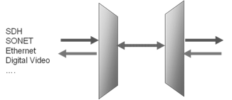
There is a lot of flexibility in how OTNs are deployed, depending on the transport services to be provided. One of the reasons for this flexibility is that most optical components are transparent to signal encoding. Only at the boundary of the optical layer, where the optical signal needs to be converted back to the electronic domain, does the encoding matter.
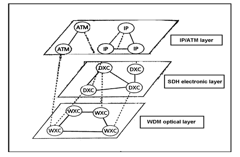
Thus, transparent optical services to support various legacy electronic network technologies, such as SDH, ATM, IP and frame relay, running on top of the optical layer, is a likely scenario in the future.
The optical layer is further divided into three sublayers −
The optical channel layer network, which interfaces with OTN clients, providing optical channels (OChs).
The optical multiplex layer network, which multiplexes various channels into a single optical signal.
The optical transmission section layer network, which provides the transmission of the optical signal across the fiber.
OTN FRAME FORMAT
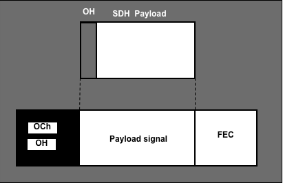
Similar to the use of a SDH frame, access to the OCh is expected to be through an OC frame, which is currently defined. The basic frame size corresponds to STM-16 speed or 2488.32 Mbps, which constitutes the basic OCh signal. The following Figure depicts a possible OCh frame format.

An Optical Channel Frame
The leftmost region of the frame (shown in the Figure given below) is reserved for overhead bytes. These bytes are to be used for OAM&P functions, similar to the overhead bytes of the SDH frame, discussed earlier.
However, additional functions are likely to be supported, such as the provision of dark fibers (reservation of a wavelength between two end points for a single user) and wavelength-based APS. The rightmost region of the frame is reserved for a forward error correction (FEC) scheme to be exercised on all payload data. An FEC over an optical transmission layer increases the maximum span length, and reduces the number of repeaters. A Reed-Solomon code can be used.
Several OChs are to be multiplexed together in the optical domain, to form the optical multiplexer signal (OMS). This parallels to the multiplexing of several STM-1 frames into an STM-N SDH frame format. Multiple OChs can be multiplexed to form OMS.
The optical client signal is placed within the OCh payload signal. Client signal is not constrained by the OCh frame format. Instead, the client signal is required to be only a constant bit rate digital signal. Its format is also irrelevant to the optical layer.
WDM RINGS
Conceptually, a WDM ring is not much different from a SDH ring. WXCs are interconnected in a ring topology, similar to SDH ADMs in a SDH-ring. The major architectural difference between a SDH ring and a WDM ring is rooted in the WXC capabilities of wavelength switching and conversion.
These features can be used for instance, to provide levels of protection with no parallel in SDH technology. In other words, wavelength or light path protection can be provided, in addition to path and line protection.
Optical APS protocols are as complex as SDH APSs. Protection can be provided either at the OCh level or the optical multiplex section/optical transmission section level. Some extra protection capabilities can be implemented with no parallel in SDH rings. For instance, a failed light path (e.g. a laser failure) can be fixed by converting an optical signal from a given wavelength into a different one, avoiding the rerouting of the signal.
This is equivalent to span switching in SDH, with the difference that even two fiber WDM rings can provide such capability for OCh protection. In the OMS layer, however, span protection will require four fiber rings, as in SDH. These extra features will undoubtedly introduce extra complexity in the optical-layer APS protocols.
Once the WDM ring is up, light paths need to be established in accordance with the traffic pattern to be supported.
MESH WDM NETWORKS
Mesh WDM networks are constructed with the same optical components as WDM rings. However, the protocols used in mesh networks are different from those used in rings. For instance, protection in mesh networks is a more complex proposition as is the problem of routing and wavelength assignment in WDM mesh networks.
Mesh networks are likely to be as backbone infrastructures connecting WDM rings. Some of these connections are expected to be optical, avoiding optical/electronic bottlenecks and providing transparency. Others will require the conversion of the optical signal into the electronic domain for monitoring management, and perhaps billing purposes. The following Figure depicts a WDM network.

Infrastructure − In this figure, three following topology layers are shown −
- Access Network
- Regional Network
- Backbone Network
WDM Network Infrastructure
Both SDH rings and passive optical networks (PONs) as access networks are included. They are generally based on a bus, or star topology and medium access control (MAC) protocol is used to coordinate transmissions among the users. No routing functionality is provided in such networks.
These architectures are practical for networks supporting at most a few hundred users over short distances. Although PONs are less expensive networks than WDM rings, due to the lack of active components and features such as wavelength routing, the lasers necessary at the PON sources make the first generation of such equipment still more expensive than SDH rings. This favors the SDH solution at the access network level, at least in the near future.
Backbone networks contain active optical components, hence providing functions such as wavelength conversion and routing. The backbone networks will have to somehow interface with legacy transport technologies, such as ATM, IP, PSTN, and SDH.
The overall scenario is depicted in the following Figure. Several types of interface involved in the figure.
Overlaying a WDM Transport Network carrying ATM/IP Traffic.
SDH Frame Encapsulation
The OCh frame must be defined so that SDH frame encapsulation can be easily done. The entire STM-16xc, for instance has to be carried as an OCh payload. If a basic STM-16 optical channel is used, it might not be possible to encapsulate SDH-16xc into STM-16 optical channel, due to the OCh overhead bytes.
The OCh frame format is currently being defined. The following Figure exemplifies SDH frame encapsulation into OCh frame.
SDH Interfaces to WDM
WDM equipment with physical SDH interfaces will deliver optical signals to SDH devices. These interfaces must be for backward compatibility with SDH technology. Therefore, the SDH device need not be aware of the WDM technology used to transport its signal (e.g. the device can belong to a BLSR/4 ring).
In this case, the WXC will drop and add into the optical medium the wavelength originally used in the SDH ring. This way, WDM and SDH layers are completely decoupled, which is necessary for WDM interoperability with SDH legacy equipment.
This puts extra constraints on the selection of wavelengths in the optical layer, since the last-hop wavelength, the one interfacing with the SDH device, must be the same one used by SDH device to terminate the optical path, if wavelength conversion is not provided within SDH device.
A WDM Link
| Technology | Detection | Restoration | Details | |
|---|---|---|---|---|
| WDM | WDM-OMS/OCH | 1-10ms | 10-30ms | Ring/P-P |
| SDH | SDH | 0.1ms | 50ms | Ring |
| APS 1+1 | 0.1ms | 50ms | P-P | |
| ATM | FDDI | 0.1ms | 10ms | Ring |
| STM | 0.1ms | 100ms | ||
| ATM PV-C/P 1+1 | 0.1ms | 10msxN | Standby N=#hops | |
| ATM PNNI SPV-C/P, SV-C/P | 40s | 1-10s | ||
| IP | Border Gateway Protocol | 180ms | 10-100s | |
| Interior Gateway Routing Protocol and E-OSPF | 40s | 1-10s | ||
| Intermediate System | 40s | 1-10s | ||
| Routing Internet Protocol | 180s | 100s |
As per the Table shown above, although restoration is faster in WDM than the SDH technology, failure detection in WDM is slower. Safer overlay of WDM/SDH protection mechanisms calls for a faster WDM protection scheme. Alternatively, SDH APSs could be artificially slowed down if SDH clients can afford the performance degradation incurred by such procedures.
Unnecessary failure recovery at higher layers may cause route instability and traffic congestion; hence, it should be avoided at all costs. Fault persistence checks can be used at higher layers to avoid early reaction to faults at lower layers.
A failure recovery at the OMS sublayer can replace recovery procedures of several instances of the SDH signals being served by optical layer. Thus, a potentially large number of SDH clients are spared from starting failure recovery procedures at their layers. Therefore, a single failure recovery at the optical OMS sublayer can spare hundreds.
Evolution towards an All-Optical Transport Network
Evolution towards an all-optical WDM network is likely to occur gradually. First, WXC devices will be connected to existing fibers. Some extra components might be necessary in the optical link, such as EDFAs, in order to make legacy fiber links suitable to WDM technology. WXCs will interface with legacy equipment, such as SDH and fiber distributed data interface (FDDI).
A plus of an all-optical transparent transport network is that the transferring of SDH functions into either the layer above (IP/ATM) or below (WDM) SDH is likely to happen, bringing savings in terms of network upgradability and maintenance. Such layer re-organization could affect transport networks, assume that real-time traffic, including voice, is packetized (IP/ATM). This could lead to the extinction of VCs' SDH signals.
A key issue then would be how to most efficiently pack packets into SDH, or even directly into OCh frames. Whatever new encapsulation method emerges, back compatibility with IP/PPP/HDLC and ATM encapsulation is a must.
NGN - Micro Electro Mechanical Systems
DWDM uses a set of optical wave lengths (or channels) around 1,553 nm with channel spacing of 0.8 nm (100 GHz), each wavelength can carry information up to 10 Gbps (STM 64). More than 100 such channels can be combined and transmitted on a single fiber. Efforts are on to squeeze the channels further and to increase data bit rate on each channel.
Experimentally, transmission of 80 channels, each carrying 40 Gbps (equivalent to 3.2 Tbits/sec) on a single fiber has been tested successfully over a length of 300 km. Deployment of point-to-point and ring-based DWDM optical network requires a newer type of network elements that can manipulate signals on the run without a costly O-E-O conversion. Optical amplifiers, filters, optical add drop multiplexers, de-multiplexers, and optical cross connect are some of the essential network elements. MEMS plays an important role in design and development of such network elements.
MEMS is an acronym for Micro Electro Mechanical Systems. It is used to create ultra-miniaturized devices, having dimensions from a few microns to a couple of centimeters across. These are quite similar to an IC, but with an ability to integrate moving mechanical parts on the same substrate.
MEMS technology has its roots in the semiconductor industry. These are fabricated using batch fabrication process similar to a VLSI. A typical MEMS is an integrated microsystem on a chip that can incorporate moving mechanical parts in addition to electrical, optical, fluidic, chemical, and biomedical elements.
Functionally, MEMS includes a variety of transudation mechanisms to convert signals from one form of energy to another.
Many different types of micro-sensors and micro-actuators can be integrated with, signal processing, optical subsystems, and micro-computing to form a complete functional system on a chip. MEMS characteristic ability is to include moving mechanical parts on the same substrate.
Due to small size, it is possible to use MEMS at places where mechanical devices are virtually impossible to put; such as, inside a blood vessel of a human body. Switching and response time of MEMS devices is also less than conventional machines and they consume lesser power.
Application of MEMS
Today, MEMS are finding application in every sphere. Telecommunication, bio-sciences, and sensors are the major beneficiaries. MEMS-based motion, acceleration, and stress sensors are being deployed massively in aircraft and spacecraft to increase safety and reliability. Pico satellites (weighing about 250 gm) are developed as inspection, communication, and surveillance devices. These use MEMS-based systems as payload as well as for their orbital control. MEMS are used in nozzles of inkjet printers, and read/write heads of hard disk drives. Automotive industry is using MEMS in fuel injection systems and airbag sensors.
Design engineers are putting MEMS in their new designs to improve performance of their products. It reduces manufacturing cost and time. Integration of multiple functions into MEMS provides higher degree of miniaturization, lower component count, and increased reliability.
Design and Fabrication Techniques
In the last few decades, the semiconductor industry has grown to its maturity. MEMS development is benefited largely by this technology. Initially, techniques and materials used for integrated circuit (IC) design and fabrication were borrowed directly for MEMS development, but now many MEMS-specific fabrication techniques are being developed. Surface micromachining, bulk micromachining, deep reactive ion etching (DRIE), and micro-molding are some of the advanced MEMS fabrication techniques.
Using the micromachining method, various layers of polysilicon, typically 1-100 mm thick, are deposited to form a three-dimensional structure having metal conductors, mirrors, and insulation layers. A precise etching process selectively removes an underlining film (sacrificial layer) leaving an overlaying film referred to as the structural layer capable of mechanical movement.
Surface micromachining is used to manufacture a variety of MEMS devices in commercial volumes. Layers of polysilicon and metal can be seen before and after the etching process.
Bulk micromachining is another widely used process to form functional components for MEMS. A single silicon crystal is patterned and shaped to form high-precision three-dimensional parts like channels, gears, membranes, nozzles, etc. These components are integrated with other parts and subsystems to produce completely functional MEMS.
Some standardized building blocks for MEMS processing and MEMS components are multi-user MEMS processes (MUMPs). These are the foundations of a platform that is leading to an application-specific approach to MEMS, very similar to the application-specific approach (ASIC), that has been so successful in the integrated circuit industry.
All Optical DWDM Networks and MEMS
Todays telecommunication experts are facing unprecedented challenge to accommodate ever-expanding array of high bandwidth services in telecommunication networks. Bandwidth demand is exponentially increasing due to expansion of Internet and Internet-enabled services. Arrival of Dense Wavelength Division Multiplexing (DWDM) has resolved this technological scarcity and altogether changed the economics of core optical network.
DWDM uses a set of optical wavelengths (or channels) around 1553 nm with channel spacing of 0.8 nm (100 GHz), each wavelength can carry information up to 10 Gbps (STM 64). More than 100 such channels can be combined and transmitted on a single fiber. Efforts are on to squeeze the channels further and to increase data bit rate on each channel.
Experimentally, transmission of 80 channels, each carrying 40 Gbits/sec (equivalent to 3.2 Tbits/sec) on a single fiber has been tested successfully over a length of 300 km. Deployment of point-to-point and ring-based DWDM optical network requires a newer type of network elements that can manipulate signals on the run without a costly O-E-O conversion. Optical amplifiers, filters, optical add drop multiplexers, de-multiplexers and optical cross connect are some of the essential network elements. MEMS plays an important role in design and development of such network elements. We will discuss Optical Add Drop Mux (OADM) and Optical Cross Connect (OXC) in detail.
Breakthrough in Optical Switching
A practical MEMS-based optical switch was demonstrated by scientists at Bell Labs during the year 1999. It functions like a seesaw bar having gold plated microscopic mirror at one end. An electrostatic force pulls the other end of the bar down, lifting the mirror which, reflects the light at a right angle. The incoming light thus moves from one fiber to the other.
The technological success is in fact a building block of variety of devices and systems, such as wavelength add/drop multiplexers, optical provisioning switches, optical cross-connect, and WDM signal equalizers.
Optical Add Drop Multiplexer
Similar to the ring-based SDH/SONET networks, the all-optical DWDM-based networks are beginning to take off. The superiority of ring-based network over mesh network has already been established by SDH network designers. In all-optical ring, bandwidths (ls) can be reserved for protection purpose. Optical Add Drop Multiplexers (OADM) are functionally similar to the SDH/SONET Add Drop Multiplexers (ADM). A group of selected wavelengths (ls) can be added or dropped from a multi wavelength light signal. OADM eliminates costly O-E-O (optical to electrical and back) conversion.
A two dimensional matrix of Optical switches as described above is used to fabricate such OADM offer very little flexibility. Re-configurable Add Drop Multiplexers (R-OADM) on the other hand allows full flexibility. Any of the channel passing through can be accessed, dropped, or new channels can be added. Wavelength of a specific channel can be changed to avoid blocking. Optical switches or OADM of this kind are known as 2D or N2 switches because the number of switching elements required are equal to the square of the number of ports, and because the light remains in a plane of two dimensions only.
An eight-port OADM requires 64 individual micro mirrors with their control on a MEMS device. It is quite similar to cross bar switches used in telephone exchanges.
Optical switches of this kind have undergone stringent mechanical and optical tests. Average insertion loss is less than 1.4 db with excellent repeatability of 0.25 db over 1 million cycles. 2D/N2 type OADM having configuration larger than 32 32 (1024 switching mirrors) become practically unmanageable and uneconomical. Multiple layers of smaller switch fabrics are used to create larger configurations.
Optical Cross Connect
TThe limitation of 2D type optical switch has been overcome by a yet innovative optical switching technology by Bell Labs. It is popularly known as Free Space 3-D MEMS or Light Beam Steering. It uses a series of dual axis micro-mirror as an optical switch. The micro-mirror is mounted on one of the axis of a set of cross-coupled gimbal rings, via a set of torsion springs. This arrangement allows the mirror to move along two perpendicular axes at any desired angle. The mirror is actuated by electrostatic force applied at four quadrants below the mirror. The complete micro-mirror unit is replicated using MEMS technology to form a switch fabric of 128 or 256 micro-mirrors.
An array of collimated input fibers is aligned to a set of mirrors that can re-direct the light by tilting the mirror in X and Y-axis to second set of mirrors aligned to collimated output fibers. By precisely aiming a set of mirror on the input and output fibers, a desired light connection can be made. This process is called light beam steering.
Switching time of 3D MEMS switch is less than 10 ms and the micro-mirrors are extremely stable. Optical cross connects based on this technology offer various unique advantages over the O-E-O type cross connects. OXC are of high capacity, scalable, truly data bit-rate and data format independent. It intelligently routes the optical channels without costly O-E-O conversion. Low footprint and power consumption are additional advantages of the all-optical switching technology.
NGN - VARIETIES of WDM
Early WDM systems transported two or four wavelengths that were widely spaced. WDM and the follow-on technologies of CWDM and DWDM have evolved well beyond this early limitation.
WDM
Traditional, passive WDM systems are wide-spread with 2, 4, 8, 12, and 16 channel counts being the normal deployments. This technique usually has a distance limitation of less than 100 km.
CWDM
Today, coarse WDM (CWDM) typically uses 20-nm spacing (3000 GHz) of up to 18 channels. The CWDM Recommendation ITU-T G.694.2 provides a grid of wavelengths for target distances up to about 50 km on single mode fibers as specified in ITU-T Recommendations G.652, G.653, and G.655. The CWDM grid is made up of 18 wavelengths defined within the range 1270 nm to 1610 nm spaced by 20 nm.
DWDM
Dense WDM common spacing may be 200, 100, 50, or 25 GHz with channel count reaching up to 128 or more channels at distances of several thousand kilometers with amplification and regeneration along such a route.
