- MATLAB Simulink - Home
- MATLAB Simulink - Introduction
- MATLAB Simulink - Environment Setup
- MATLAB Simulink - Starting Simulink
- MATLAB Simulink - Blocks
- MATLAB Simulink - Lines
- MATLAB Simulink - Build & Simulate Model
- MATLAB Simulink - Signals Processing
- MATLAB Simulink - Adding Delay To Signals
- MATLAB Simulink - Mathematical Library
- Build Model & Apply If-else Logic
- MATLAB Simulink - Logic Gates Model
- MATLAB Simulink - Sinewave
- MATLAB Simulink - Function
- MATLAB Simulink - Create Subsystem
- MATLAB Simulink - For Loop
- MATLAB Simulink - Export Data
- MATLAB Simulink - Script
- Solving Mathematical Equation
- First Order Differential Equation
MATLAB Simulink - Logic Gates Model
In this chapter, let us understand how to build a model that demonstrates the logic gates.
For example, gates like OR, AND, XOR etc.
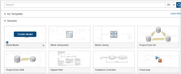
Open the Simulink and open a blank model as shown below −
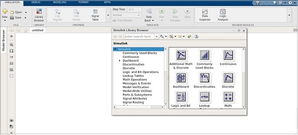
Click on blank model and select the Simulink library as shown below −
Let us select the block that we want to build a OR gate. We need two constant blocks to act as inputs, a logic operator block and a display block.
The constant and logic operator block will get from commonly used blocks library. Select the blocks and drag in your model or just type the name of the block in your model and select the block as shown below −
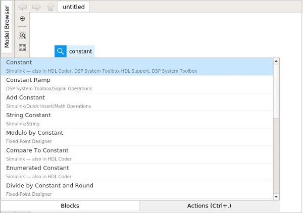
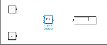
Select the constant block, we need two constant block, a logical operator and a constant.
The blocks will look as shown below −
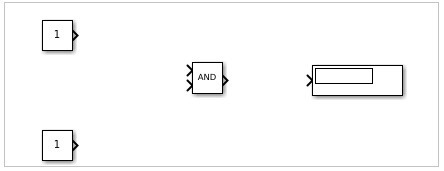
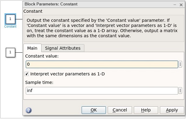
Right click on the logic operator block and it will display the block parameters as shown below −
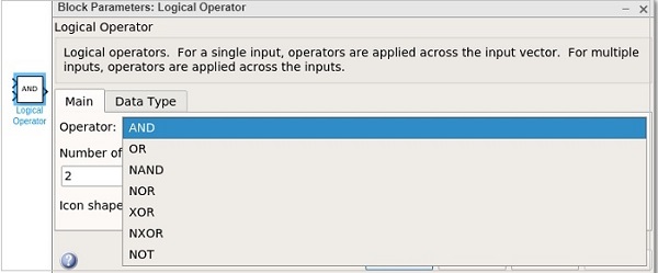
With logical operator you can use AND, OR, NAND, NOR, XOR, NXOR and NOT gates. Right now we are going to select the OR gate.
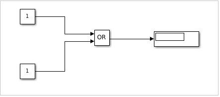
Now connect the lines and the model will be as shown below −
For an OR gate if the inputs are 1,1 the output will be 1. If the inputs are 0,0 the output will be 0. Right now, the constant has values 1,1. Let us run the model to see the output as shown below −
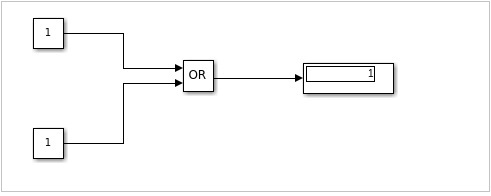
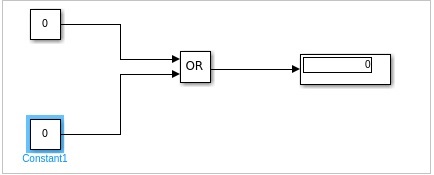
We can see in the display block the output shown is 1. Let us now change the constant value to 0. Right click on constant block and change the value as shown below −
After changing the values of constant to 0, the output will become 0 when you run the model. The output is as shown below −
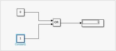
Let us now change the constant values to 0,1 and see the output −
With values as 1,0, the display will be as follows −
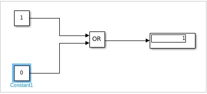
Similarly, you can design the AND and other gates.
