- MATLAB Simulink - Home
- MATLAB Simulink - Introduction
- MATLAB Simulink - Environment Setup
- MATLAB Simulink - Starting Simulink
- MATLAB Simulink - Blocks
- MATLAB Simulink - Lines
- MATLAB Simulink - Build & Simulate Model
- MATLAB Simulink - Signals Processing
- MATLAB Simulink - Adding Delay To Signals
- MATLAB Simulink - Mathematical Library
- Build Model & Apply If-else Logic
- MATLAB Simulink - Logic Gates Model
- MATLAB Simulink - Sinewave
- MATLAB Simulink - Function
- MATLAB Simulink - Create Subsystem
- MATLAB Simulink - For Loop
- MATLAB Simulink - Export Data
- MATLAB Simulink - Script
- Solving Mathematical Equation
- First Order Differential Equation
Build Model & Apply If-else Logic
In this chapter, we will create a model and apply if-else logic to it. Let us first collect blocks to create our model.
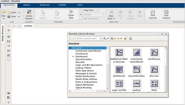
Now, open MATLAB Simulink (blank model) and the Simulink library browser as shown below −
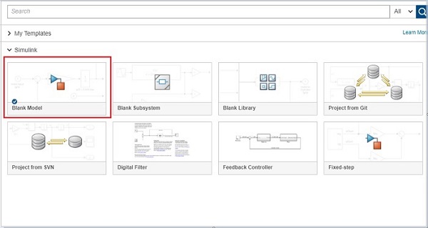
Click on the Blank Model and open Simulink library browser as shown below −
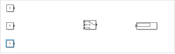
The blocks we require to build the model with if-else logic is as follows −
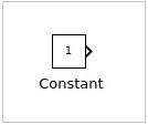
Constant block from Commonly used blocks
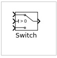
Switch block from Signal Routing
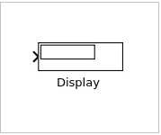
Display block from Sinks
Let us now get all the blocks together to create a model as shown below −
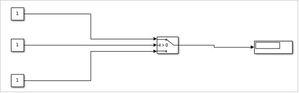
Let us now connect the lines with each block. So you can see that the constant block has one output and the switch has three inputs and one output. We are going to connect them to the display block.
After connecting the lines, the model is as shown below −
Now, double click the switch block and add a threshold.
The threshold value will be compared with the block in the center. Based on the constant value of the middle block, the first block value will be displayed or the last constant block value will be displayed.
Let us add a threshold value to the switch as shown below −
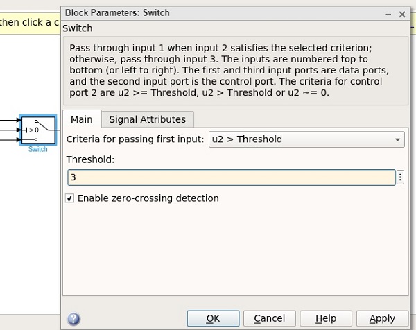
The threshold value given is 3. Click on OK to update the threshold. Now the threshold value is seen inside the switch block as shown below −
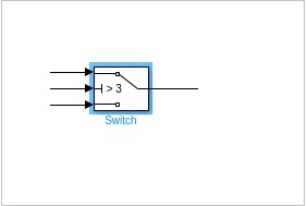
The middle constant block will be compared with the switch threshold and accordingly the display will be decided.
Let us now update the middle constant block with some value as shown below −
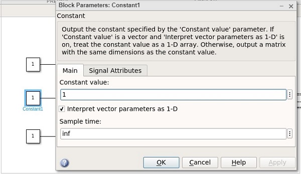
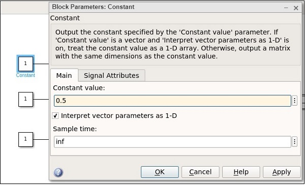
The value of the constant block is 1. Let us now change the first constant block and give it a value as 0.5 as shown below −
Let us now change the last constant with value as 2.5 as shown below −
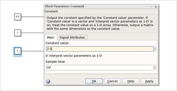
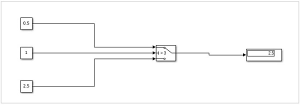
Hence, the first constant value is 0.5, the middle constant value is 1 and the last one is 2.5. The middle constant value 1 will be compared to switch threshold value i.e. 3 as (1 >3). It will print the value as 2.5 the last constant value.
Click on the run button to get the output in the display block as shown below −
Let us now change the middle constant to a higher value than the threshold of switch and see the output −
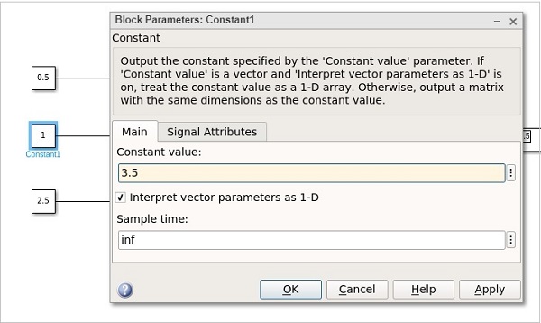
The value is changed from 1 to 3.5. Click on OK and run the model to see the output in the display −
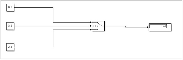
Now, since the value of the middle constant is greater, the value from the first constant is printed in display. If it is less, then the value from the last constant will be printed.
