
Article Categories
- All Categories
-
 Data Structure
-
 Networking
-
 RDBMS
RDBMS
-
 Operating System
-
 Java
Java
-
 MS Excel
-
 iOS
iOS
-
 HTML
HTML
-
 CSS
CSS
-
 Android
-
 Python
-
 C Programming
-
 C++
C++
-
 C#
C#
-
 MongoDB
-
 MySQL
MySQL
-
 Javascript
-
 PHP
PHP
-
 Economics & Finance
Getting data from Vibration sensor using Arduino
In this tutorial, we will interface Arduino with the MPU6050 Vibration sensor.
Circuit Diagram
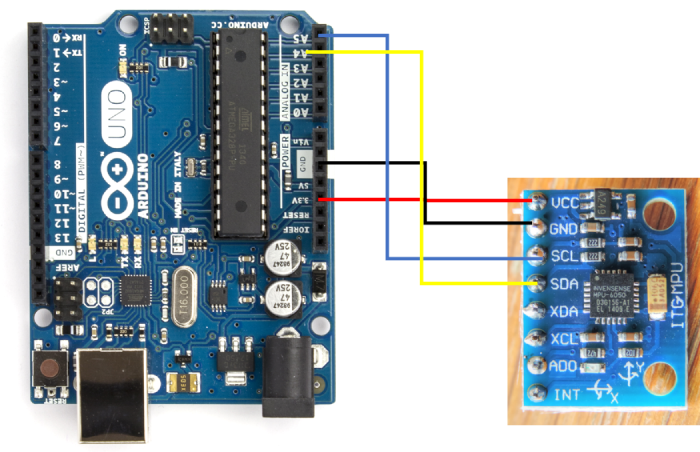
As you can see, we connect Vcc to 3.3V, GND to GND, SDA to A4 and SCL to A5. A4 and A5 also serve as SDA and SCL on Arduino Uno.
Code Walkthrough
The code is given below −
#include<Wire.h>

const int MPU_ADDR = 0x68; // I2C address of the MPU-6050
int16_t AcX, AcY, AcZ, Tmp, GyX, GyY, GyZ;

void setup() {
   Serial.begin(9600);
   Wire.begin();
   Wire.beginTransmission(MPU_ADDR);
   Wire.write(0x6B); // PWR_MGMT_1 register
   Wire.write(0); // set to zero (wakes up the MPU-6050)
   Wire.endTransmission(true);
   Serial.println("Setup complete");
}

void loop() {
   Wire.beginTransmission(MPU_ADDR);
   Wire.write(0x3B); // starting with register 0x3B (ACCEL_XOUT_H)
   Wire.endTransmission(true);
   Wire.beginTransmission(MPU_ADDR);
   Wire.requestFrom(MPU_ADDR, 14, true); // request a total of 14 registers
   AcX = Wire.read() << 8 | Wire.read(); // 0x3B (ACCEL_XOUT_H) & 0x3C (ACCEL_XOUT_L)
   AcY = Wire.read() << 8 | Wire.read(); // 0x3D (ACCEL_YOUT_H) & 0x3E (ACCEL_YOUT_L)
   AcZ = Wire.read() << 8 | Wire.read(); // 0x3F (ACCEL_ZOUT_H) & 0x40 (ACCEL_ZOUT_L)
   Tmp = Wire.read() << 8 | Wire.read(); // 0x41 (TEMP_OUT_H) & 0x42 (TEMP_OUT_L)
   GyX = Wire.read() << 8 | Wire.read(); // 0x3B (ACCEL_XOUT_H) & 0x3C (ACCEL_XOUT_L)
   GyY = Wire.read() << 8 | Wire.read(); // 0x3D (ACCEL_YOUT_H) & 0x3E (ACCEL_YOUT_L)
   GyZ = Wire.read() << 8 | Wire.read(); // 0x3F (ACCEL_ZOUT_H) & 0x40 (ACCEL_ZOUT_L)

   Serial.print(AcX); Serial.print(" , ");
   Serial.print(AcY); Serial.print(" , ");
   Serial.print(AcZ); Serial.print(" , ");
   Serial.print(GyX); Serial.print(" , ");
   Serial.print(GyY); Serial.print(" , ");
   Serial.print(GyZ); Serial.print("<br>");
}
We begin with the inclusion of the Wire.h library
#include<Wire.h>
Next, we define the I2C Address of the MPU6050 chip (0x68) and the variables to store the 3 acceleration and 3 gyroscope values, and a temp variable to store an intermediate value.
const int MPU_ADDR = 0x68; // I2C address of the MPU-6050
int16_t AcX, AcY, AcZ, Tmp, GyX, GyY, GyZ;
Within setup, we initialize Serial, then initialize Wire, and then Wake the MPU6050 by writing 0 to the 0x6B (power management) register.
void setup() {
   Serial.begin(9600);
   Wire.begin();
   Wire.beginTransmission(MPU_ADDR);
   Wire.write(0x6B); // PWR_MGMT_1 register
   Wire.write(0); // set to zero (wakes up the MPU-6050)
   Wire.endTransmission(true);
   Serial.println("Setup complete");
}
Within the loop, we start reading 14 bytes from the 0x3B register. As mentioned in the MPU6050’s datasheet, starting from 0x3B register, we have the higher and lower bytes of Xaxis acceleration, higher and lower bytes of Y-axis acceleration, and the two bytes for the Zaxis acceleration. This is followed by two bytes for temperature, and then two bytes each (higher and lower) for X, Y and Z direction gyroscopic readings. Thus, we read the values and store them accordingly, and then print them. The X and Y directions are indicated on the MPU6050 and the Z direction is perpendicular to the board.
void loop() {
   Wire.beginTransmission(MPU_ADDR);
   Wire.write(0x3B); // starting with register 0x3B (ACCEL_XOUT_H)
   Wire.endTransmission(true);
   Wire.beginTransmission(MPU_ADDR);
   Wire.requestFrom(MPU_ADDR, 14, true); // request a total of 14 registers
   AcX = Wire.read() << 8 | Wire.read(); // 0x3B (ACCEL_XOUT_H) & 0x3C (ACCEL_XOUT_L)
   AcY = Wire.read() << 8 | Wire.read(); // 0x3D (ACCEL_YOUT_H) & 0x3E (ACCEL_YOUT_L)
   AcZ = Wire.read() << 8 | Wire.read(); // 0x3F (ACCEL_ZOUT_H) & 0x40 (ACCEL_ZOUT_L)
   Tmp = Wire.read() << 8 | Wire.read(); // 0x41 (TEMP_OUT_H) & 0x42 (TEMP_OUT_L)
   GyX = Wire.read() << 8 | Wire.read(); // 0x3B (ACCEL_XOUT_H) & 0x3C (ACCEL_XOUT_L)
   GyY = Wire.read() << 8 | Wire.read(); // 0x3D (ACCEL_YOUT_H) & 0x3E (ACCEL_YOUT_L)
   GyZ = Wire.read() << 8 | Wire.read(); // 0x3F (ACCEL_ZOUT_H) & 0x40 (ACCEL_ZOUT_L)

   Serial.print(AcX); Serial.print(" , ");
   Serial.print(AcY); Serial.print(" , ");
   Serial.print(AcZ); Serial.print(" , ");
   Serial.print(GyX); Serial.print(" , ");
   Serial.print(GyY); Serial.print(" , ");
   Serial.print(GyZ); Serial.print("<br>");
}
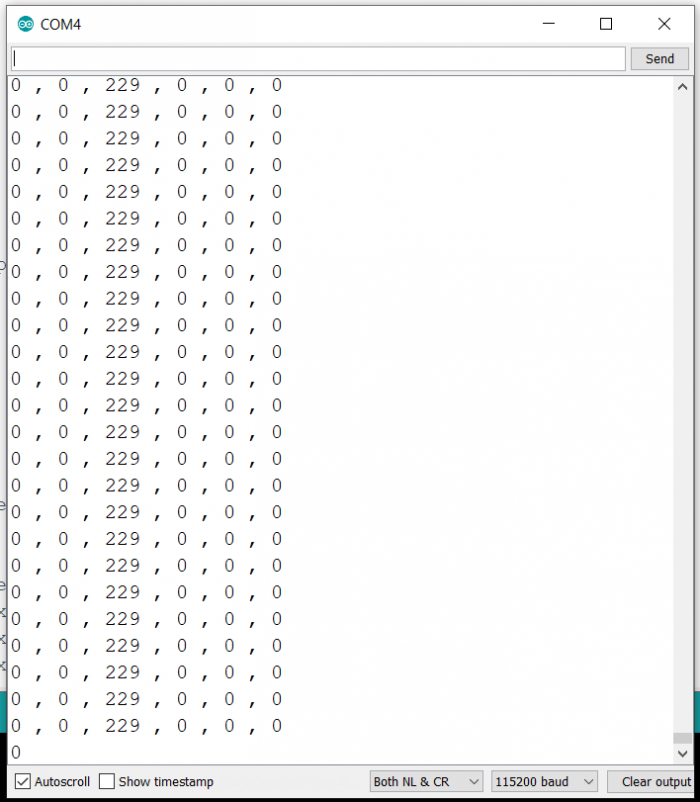
Output
The Serial Monitor output will be similar to the one shown below −

3K+ Views
