
Article Categories
- All Categories
-
 Data Structure
-
 Networking
-
 RDBMS
RDBMS
-
 Operating System
-
 Java
Java
-
 MS Excel
-
 iOS
iOS
-
 HTML
HTML
-
 CSS
CSS
-
 Android
-
 Python
-
 C Programming
-
 C++
C++
-
 C#
C#
-
 MongoDB
-
 MySQL
MySQL
-
 Javascript
-
 PHP
PHP
-
 Economics & Finance
Unconditional call and return instructions in 8085 Microprocessor
Sometimes in 8085assembly language coding, we require to repeat a certain program segment for multiple times. In those situations, we can define sub-routines. In those subroutines, we can enclose our repeatedly reusable Instruction set or code. And then as when required we shall call those sub-routines accordingly. Sub-routines can also be called as procedures.
Whenever the instructions in a subroutine are required to be executed, we branch program control to the subroutine using th CALL instruction. CALL is a 3-Byte instruction, with 1 Byte for the opcode, and 2 Bytes for the address of the subroutine. CALL mnemonics stands for “call a subroutine”. After executing the instructions written in the subroutine we shall want to return control to the next instruction written after the CALL instruction then we shall use mnemonic RET. Here RET stands for RETurn from the subroutine. RETis a 1-Byte instruction. In the following table, we have mentioned the code and Byte count for CALL and RET instructions –
| Mnemonics, Operand |
Opcode(in HEX) |
Bytes |
|---|---|---|
| CALL Label |
CD |
3 |
| RET |
C9 |
1 |
Let us consider the following sample code for a better explanation –
| Address |
Hex Codes |
Mnemonic |
Comment |
|---|---|---|---|
| 2000 |
31 |
LXI SP, 5000H |
SP ← 5000H.Initializing the SP |
| 2001 |
00 |
|
Low order Byte of the address |
| 2002 |
50 |
|
High order Byte of the address |
| 2003 |
3E |
MVI A, 00H |
A ← 00H, Initializing the Accumulator |
| 2004 |
00 |
|
00H as operand |
| 2005 |
06 |
MVI B, 01H |
B ← 01H |
| 2006 |
01 |
|
01H as operand |
| 2007 |
0E |
MVI C, 02H |
C ← 02H |
| 2008 |
02 |
|
02H as operand |
| 2009 |
16 |
MVI D, 03H |
D ← 03H |
| 200A |
03 |
|
03H as operand |
| 200B |
CD |
CALL 2013H |
Calling the subroutine at address 2013H. So now the control of the program will be transferred to the location2013H. And the return address 200EH i.e. address of the next instruction will be pushed on the top of the stack. As a result4FFFH (SP – 1) will contain 20H and 4FFEH (SP – 2) will contain 0EH respectively. |
| 200C |
13 |
|
Low order Byte of the address |
| 200D |
20 |
|
High order Byte of the address |
| 200E |
21 |
LXI H, 4050H |
HL ← 4050H,Initializing the HL register pair. After execution of the RETinstruction, control will come back to this instruction. 4050Hwill have the value 06H, i.e. the final sum of 01H + 02H + 03H =06H |
| 200F |
50 |
|
Low order Byte of the address |
| 2010 |
40 |
|
High order Byte of the address |
| 2011 |
77 |
MOV M, A |
M ← A, Content of the Accumulator will be transferred to the memory location 4050H as it is pointed by HL register pair |
| 2012 |
76 |
HLT |
End of the program. |
| 2013 |
80 |
ADD B |
A ← A + B |
| 2014 |
81 |
ADD C |
A ← A + C |
| 2015 |
82 |
ADD D |
A ← A + D |
| 2016 |
C9 |
RET |
Return the control to the address 200EH. Return address 200EH will be popped out from the top of the stack. So from address 4FFEH, 0EH will be popped and from address 4FFFH 20Hwill be popped and SP will get the initial address 5000H back as its content accordingly. |
The timing diagram against this instruction CALL 2013H execution is as follows –

Summary − So this instruction CALL requires 3-Bytes, 5-Machine Cycles (Opcode Fetch, MemoryRead, Memory Read, Memory Write, Memory Write) and 18 T-States for execution as shown in the timing diagram.
The timing diagram against this instruction RET execution is as follows –
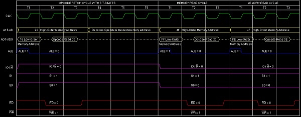
Summary − So this instruction RET requires 1-Byte, 5-Machine Cycles (Opcode Fetch, Memory Read, MemoryRead) and 10 T-States for execution as shown in the timing diagram.

16K+ Views
