
Article Categories
- All Categories
-
 Data Structure
-
 Networking
-
 RDBMS
RDBMS
-
 Operating System
-
 Java
Java
-
 MS Excel
-
 iOS
iOS
-
 HTML
HTML
-
 CSS
CSS
-
 Android
-
 Python
-
 C Programming
-
 C++
C++
-
 C#
C#
-
 MongoDB
-
 MySQL
MySQL
-
 Javascript
-
 PHP
PHP
-
 Economics & Finance
Difference between call and jump instructions in 8085 Microprocessor
The main differences between a JMP instruction and a CALL instruction is as follows –
If a JMP instruction is executed, we jump to the destination location, and the execution carries on from there, without bothering to come back later to the instruction after the JMP. On the other hand, if a CALL instruction is executed, we jump to the subroutine, and the execution carries on from there till the RET instruction is executed in the subroutine, and then we come back to the instruction after the CALL in the main program.
The address of the next instruction after the CALL instruction is called the return address. This is the address to which the program flow returns when the RET instruction is executed by the 8085. By the time the 8085 fetches the call instruction, the PC would have been incremented by 3, and will be pointing to the next instruction after call. In other words, PC will have the return address by the time the call instruction is fetched.
In order to facilitate such a return, the CALL instruction will first of all store above the top of stack, the return address. Only then the branch to the subroutine takes place.
We are having different types of conditional and unconditional JUMP instructions in 8085. Here are the details –
In 8085 Instruction set, there are a set of jump instructions, which can transfer program control to a certain memory location. So after these branching mnemonics we shall have to mention 16-bit target address of the location. These jump instructions can be divided into two categories –
Unconditional jump instructions and
Conditional jump instructions
Under unconditional jump instructions there is only one mnemonic i.e. JUMP. But under conditional Jump instructions we are having 8 different mnemonics. We know that there are 5 flag bits in 8085 Flag register. They are S, Z, P, Cy, AC. Out of them only on AC flag bit, there is no jump instruction. But for rest 4 flag bits, we are having 8 conditional jump instructions depending upon their 1 or 0 i.e. TRUE and FALSE values respectively. Here is the list of all branching instructions in the following table –
|
Mnemonics, Operand |
Opcode (in HEX) |
Bytes |
|---|---|---|
| JC Label |
DA |
3 |
| JM Label |
FA |
3 |
| JMP Label |
C3 |
3 |
| JNC Label |
D2 |
3 |
| JNZ Label |
C2 |
3 |
| JP Label |
F2 |
3 |
| JPE Label |
EA |
3 |
| JPO Label |
E2 |
3 |
| JZ Label |
CA |
3 |
The following table shows the list of Branching instructions with their meanings.
|
Opcode |
Operand |
Meaning |
Explanation |
|||||||||||||||||||||||||||
|---|---|---|---|---|---|---|---|---|---|---|---|---|---|---|---|---|---|---|---|---|---|---|---|---|---|---|---|---|---|---|
|
JMP |
16-bit address |
Jump unconditionally |
The program sequence is transferred to the memory address given in the operand. |
|||||||||||||||||||||||||||
|
16-bit address |
Jump conditionally |
The program sequence is transferred to the memory address given in the operand based on the specified flag of the PSW. |
The main purpose and usage of CALL instruction has been depicted below –
Some times in 8085 assembly language coding, we require to repeat a certain program segment for multiple times. In those situations, we can define sub-routines. In those subroutines we can enclose our repeatedly reusable Instruction set or code. And then as when required we shall call those sub-routines accordingly. Sub-routines can also be called as procedures.
Whenever the instructions in a subroutine are required to be executed, we branch program control to the subroutine using the CALL instruction. CALL is a 3-Byte instruction, with 1 Byte for the opcode, and 2 Bytes for the address of subroutine. CALL mnemonics stands for “call a subroutine”. After executing the instructions written in the subroutine we shall want to return control to the next instruction written after the CALL instruction then we shall use mnemonic RET. Here RET stands for RETurn from subroutine. RET is a 1-Byte instruction. In the following table we have mentioned Opcode and Byte count for CALL and RET instructions –
|
Mnemonics, Operand |
Opcode (in HEX) |
Bytes |
|---|---|---|
| CALL Label |
CD |
3 |
| RET |
C9 |
1 |
Let us consider the following sample code for better explanation –
|
Address |
Hex Codes |
Mnemonic |
Comment |
|---|---|---|---|
| 2000 |
31 |
LXI SP, 5000H |
SP ← 5000H. Initializing the SP |
| 2001 |
00 |
Low order Byte of the address |
|
| 2002 |
50 |
High order Byte of the address |
|
| 2003 |
3E |
MVI A, 00H |
A ← 00H, Initializing the Accumulator |
| 2004 |
00 |
00H as operand |
|
| 2005 |
06 |
MVI B, 01H |
B ← 01H |
| 2006 |
01 |
01H as operand |
|
| 2007 |
0E |
MVI C, 02H |
C ← 02H |
| 2008 |
02 |
02H as operand |
|
| 2009 |
16 |
MVI D, 03H |
D ← 03H |
| 200A |
03 |
03H as operand |
|
| 200B |
CD |
CALL 2013H |
Calling the sub routine at address 2013H. So now the control of the program will be transferred to the location 2013H. And the return address 200EH i.e. address of the next instruction will be pushed on the top of the stack. As a result 4FFFH (SP – 1) will contain 20H and 4FFEH (SP – 2) will contain 0EH respectively . |
| 200C |
13 |
Low order Byte of the address |
|
| 200D |
20 |
High order Byte of the address |
|
| 200E |
21 |
LXI H, 4050H |
HL ← 4050H, Initializing the HL register pair. After execution of the RET instruction, control will come back to this instruction. 4050H will have the value 06H, i.e. the final sum of 01H + 02H + 03H = 06H |
| 200F |
50 |
Low order Byte of the address |
|
| 2010 |
40 |
High order Byte of the address |
|
| 2011 |
77 |
MOV M, A |
M ← A, Content of the Accumulator will be transferred to the memory location 4050H as it is pointed by HL register pair |
| 2012 |
76 |
HLT |
End of the program. |
| 2013 |
80 |
ADD B |
A ← A + B |
| 2014 |
81 |
ADD C |
A ← A + C |
| 2015 |
82 |
ADD D |
A ← A + D |
| 2016 |
C9 |
RET |
Return the control to the address 200EH. Return address 200EH will be popped out from the top of the stack. So from address 4FFEH, 0EH will be popped and from address 4FFFH 20H will be popped and SP will get the initial address 5000H back as its content accordingly. |
The timing diagram against this instruction CALL 2013H execution is as follows –
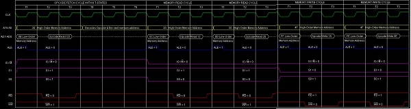
Summary: So this instruction CALL requires 3-Bytes, 5-Machine Cycles (Opcode Fetch, Memory Read, Memory Read, Memory Write, Memory Write) and 18 T-States for execution as shown in the timing diagram.
The timing diagram against this instruction RET execution is as follows –
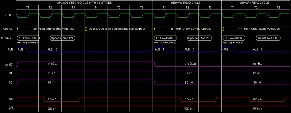
Summary: So this instruction RET requires 1-Byte, 5-Machine Cycles (Opcode Fetch, Memory Read, Memory Read) and 10 T-States for execution as shown in the timing diagram.
.

4K+ Views
