
Article Categories
- All Categories
-
 Data Structure
-
 Networking
-
 RDBMS
RDBMS
-
 Operating System
-
 Java
Java
-
 MS Excel
-
 iOS
iOS
-
 HTML
HTML
-
 CSS
CSS
-
 Android
-
 Python
-
 C Programming
-
 C++
C++
-
 C#
C#
-
 MongoDB
-
 MySQL
MySQL
-
 Javascript
-
 PHP
PHP
-
 Economics & Finance
Diac Operations and Applications
A diac is a two-terminal, three-layer, bidirectional device which can be switched from OFF state to ON state for both positive and negative polarity of the supply voltage.
Constructional Details of the Diac

The basic structure of a Diac is similar to a BJT transistor. The only difference is that there is no base terminal in case of Diac.
The terminals of the diac are taken from the two p-regions of silicon that are separated by an n-region. The concentrations are identical in all layers to give the device symmetrical properties.
V – Characteristics of Diac
From I-V Characteristics of a Diac, for the applied voltage less than IBO, a small leakage current (IBO) flows through the device. Under such condition, the Diac blocks the current flow and acts as an open circuit. The voltage VBO is the break – over voltage and its value ranges from 30 V to 50 V.
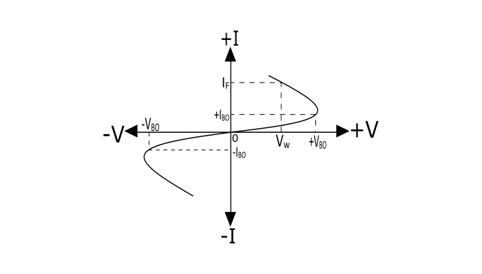
Operation of the Diac
The amount of voltage required across the terminals of the diac to switch it ON is called the Break-Over Voltage (IBO). Once the diac is made ON, the only way to switch it off is to reduce the current to zero by isolating it from the supply.
When a small positive or negative voltage is applied across the terminals of the diac, a small leakage current IBO will flow through the diac. This is because one pn-junction is reverse biased. When the applied voltage is increased gradually, the leakage current will continue to flow until the voltage attains value equal to the Break-Over Voltage (IBO). At point of break over voltage, avalanche breakdown occurs on the reverse biased junction and the current through the diac increases with the decreasing value of applied voltage. The voltage across the diac drops to the Break – Back Voltage (VW).
When the applied voltage is equal to or greater than the breakdown voltage, the Diac starts to conduct and the voltage drop across it becomes a few volts.
Applications of the Diac
- Diacs are primarily used in the triggering circuits of the Triacs
- Lamp dimmer circuits
- Heat control circuits
- Speed control of universal motors

8K+ Views
