
Article Categories
- All Categories
-
 Data Structure
-
 Networking
-
 RDBMS
RDBMS
-
 Operating System
-
 Java
Java
-
 MS Excel
-
 iOS
iOS
-
 HTML
HTML
-
 CSS
CSS
-
 Android
-
 Python
-
 C Programming
-
 C++
C++
-
 C#
C#
-
 MongoDB
-
 MySQL
MySQL
-
 Javascript
-
 PHP
PHP
-
 Economics & Finance
Decoder for Active Low and High Output
What is a Decoder?
In digital electronics, a decoder is a combinational logic circuit which is capable of converting information in binary form N inputs to a maximum of 2N outputs. The block diagram of a typical decoder is shown in Figure-1.
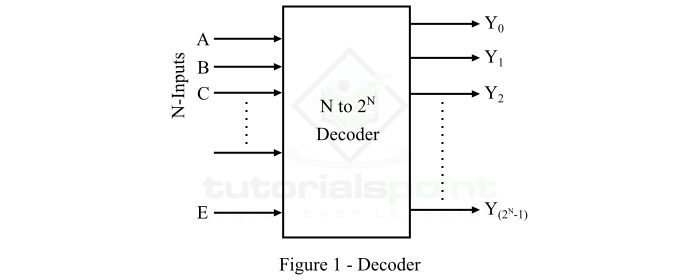
It can be seen that a decoder has N input lines to accept binary coded information, an enable input, E to turn on or off the decoder (optional), and 2N unique output lines.
The digital decoders are extensively used in several applications in the field of digital electronics such as decoding of data, seven segment displays, data multiplexing and demultiplexing, memory operations, etc.
Active Low and Active High
In digital logic, there two states of a digital signal namely, Active Low and Active High.
In Active Low State, the digital signal is considered high or active or on, when it is in a logic 0 level or in logic low state. On the other hand, when the signal is considered high or active or on, when it is in a logic 1 level or logic high state, it called Active High state of the signal.
Now, let us understand the operation of a decoder for active low and active high output. For that we consider a 2 to 4 line decoder which is having two inputs (let A and B) and four outputs, i.e. Y0, Y1, Y2, and Y3. So, let us start with the decoder for active low output.
What is an Active Low Decoder?
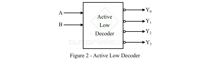
The type of decoder that converts a binary input code into a specific output code/signal as per the input combinations, where the output of the decoder is considered active or ON when it is in the logic 0 state, it called an active low decoder. The block diagram representation of the 2 to 4 line active low decoder is shown in Figure-2.
The truth table of the active low 2 to 4 line decoder is given below ?
| Inputs | Outputs | ||||
|---|---|---|---|---|---|
| A | B | Y0 | Y1 | Y2 | Y3 |
| 0 | 0 | 0 | 1 | 1 | 1 |
| 0 | 1 | 1 | 0 | 1 | 1 |
| 1 | 0 | 1 | 1 | 0 | 1 |
| 1 | 1 | 1 | 1 | 1 | 0 |
From the truth table, we can see that
The output Y0 is active (Low) when both inputs A and B are low.
The output Y1 is active (Low) when the input A is low and B is high.
The output Y2 is active (Low) when the input A is high and B is low.
The output Y3 is active (Low) when the input A is high and B is high.
From the truth table, we can see the output of the decoder is considered active when it is in low state, i.e. in logic 0 state. For this reason it is called an active low decoder. We can directly write the expression of each output of the active low decoder as follows ?
$$Y_{0}\, =\left ( A+B \right )$$
$$Y_{1}\, =\left ( A+\bar{B} \right )$$
$$Y_{2}\, =\left ( \bar{A}+B \right )$$
$$Y_{3}\, =\left ( \bar{A}+\bar{B} \right )$$
Now, let us discuss the active high decoder.
What is an Active High Decoder?
The type of decoder that converts a binary input code into a specific output code/signal as per the input combinations, where the output of the decoder is considered active or ON when it is in the logic 1 state, it called an active high decoder. The block diagram representation of the 2 to 4 line active high decoder is shown in Figure-3.

The truth table of the 2 to 4 line active high decoder is given below ?
| Inputs | Outputs | ||||
|---|---|---|---|---|---|
| A | B | Y0 | Y1 | Y2 | Y3 |
| 0 | 0 | 1 | 0 | 0 | 0 |
| 0 | 1 | 0 | 1 | 0 | 0 |
| 1 | 0 | 0 | 0 | 1 | 0 |
| 1 | 1 | 0 | 0 | 0 | 1 |
From the truth table, we can see that
The output Y0 is active (high) when both inputs A and B are low.
The output Y1 is active (high) when the input A is low and B is high.
The output Y2 is active (high) when the input A is high and B is low.
The output Y3 is active (high) when both inputs A and B are high.
From the truth table, we can see the output of the decoder is considered active when it is in high state or in logic 1 state. For this reason it is called an active high decoder. We can directly write the expression of each output of the active high decoder as follows ?
$$Y_{0}=\bar{A}\bar{B}$$
$$Y_{1}=\bar{A}B$$
$$Y_{2}=A\bar{B}$$
$$Y_{3}=AB$$
This is all about decoder for active low output and active high output.

20K+ Views
