
Article Categories
- All Categories
-
 Data Structure
-
 Networking
-
 RDBMS
RDBMS
-
 Operating System
-
 Java
Java
-
 MS Excel
-
 iOS
iOS
-
 HTML
HTML
-
 CSS
CSS
-
 Android
-
 Python
-
 C Programming
-
 C++
C++
-
 C#
C#
-
 MongoDB
-
 MySQL
MySQL
-
 Javascript
-
 PHP
PHP
-
 Economics & Finance
Decimal addition in 8085 Microprocessor
In a digital computer, everything is represented using 0s and 1s only. For example, instruction will have a code using only 0s and 1s. Data is also represented using 0s and 1s. Data can be of different types like unsigned numbers, signed numbers, floating point numbers, binary coded decimal (BCD) numbers, etc. Thus, a series of 0s and 1s will acquire a value based on the interpretation. For decimal addition, we are having a very important and common instruction DAD. Let us discuss more on that instruction now.
In spite of the fact that 8085 is an 8-bit microprocessor, but there are some instructions are there available in the 8085 instruction set which can do 16-bit additions also. As the 8085 internal architecture is only 8-bits, this instruction easily takes double the time needed to add two 8-bit numbers.
Here, DAD is a mnemonic, which stands for Double ADd and also rp stands for any one of the following register pairs as mentioned below –
rp = BC, DE, or HL
As rp can have any of the three values, there are three opcodes for this type of instruction. It occupies only 1-Byte in memory.
|
Mnemonics, Operand |
Opcode (in HEX) |
Bytes |
|---|---|---|
| DAD B |
09 |
1 |
| DAD D |
19 |
1 |
| DAD H |
29 |
1 |
In this instruction, HL register pair works as Accumulator. Because the 16-bit content of rp will be added with HL register pair content and sum thus produced will be stored back on to HL again.
Though it is an arithmetic instruction, by design, flags other than Cy, will not get affected by the execution of this instruction DAD rp.
Let us consider DAD B is a sample instruction of this category. It is 1-Byte instruction so it occupies a single Byte place in the memory. We are considering the initial content of HL and BC register pairs are 4050H and 4060H. So after 16-bit addition, the current content of HL register pair will be 80B0H. The result of execution of this instruction is shown below with a tracing table –
|
Before |
After |
|
|---|---|---|
|
(HL) |
4050H |
80B0H |
|
(BC) |
4060H |
4060H |
|
(F) |
Any values |
Cy=0, no change on other flag bits |
|
Address |
Hex Codes |
Mnemonic |
Comment |
|---|---|---|---|
| 2006 |
09 |
DAD B |
HL = HL + BC |
The timing diagram against this instruction DAD B execution is as follows –
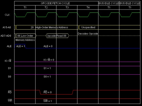
Summary: So this instruction DAD B requires 1-Byte, 3 Machine Cycle (Opcode Fetch, Bus Idle, Bus Idle) and 10 T-States for execution as shown in the timing diagram. This instruction takes 10 T states including opcode fetch. The opcode fetch cycle takes 4 T states and the remaining 6 T states, divided into two Machine Cycles, are for the instruction execution. During these 6 T (two Machine Cycles) states no bus operations are performed. Hence they are called bus idle Machine Cycles. During this ALE, RD etc. are not activated.

2K+ Views
