
Article Categories
- All Categories
-
 Data Structure
-
 Networking
-
 RDBMS
RDBMS
-
 Operating System
-
 Java
Java
-
 MS Excel
-
 iOS
iOS
-
 HTML
HTML
-
 CSS
CSS
-
 Android
-
 Python
-
 C Programming
-
 C++
C++
-
 C#
C#
-
 MongoDB
-
 MySQL
MySQL
-
 Javascript
-
 PHP
PHP
-
 Economics & Finance
Flags register in 8085 Microprocessor
In 8085 microprocessor, the flags register can have a total of eight flags. Thus a flag can be represented by 1 bit of information. But only five flags are implemented in 8085. And they are:
Carry flag (Cy),
Auxiliary carry flag (AC),
Sign flag (S),
Parity flag (P), and
Zero flag (Z).
The respective position of these flag bits in flag register has been show the below figure. The positions marked by "x" are to be considered as don't care bits in the flags register. The user is not required to memorize the positions of these flags in the flags register.

Fig. Flags register
Now consider the programmer's view of 8085 contains the flags register has been depicted in the following figure -
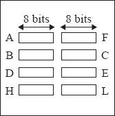
Fig. Programmer's view of 8085 Flags register
These individual flags are either set to 1, or reset to 0 depending on the result of execution of the last executed arithmetic or logical instruction. But in a few arithmetic and logical instructions, some or none of these flags are affected. Also there are some arithmetic and logical instructions, flag bits in the flag register will not get affected as well. As example in the execution of DCX and INX instructions, flag bit in flag register will not get affected at all.
However, in any data transfer instruction, none of the flags bits in flag register are affected. Now let us consider each flag bit separately for our further discussions.
Carry flag (Cy): after performing the addition of any two 8-bit numbers, the carry generated can be either 0 or 1. That is only 1-bit. Thus to store the carry information 1-bit storage is enough. The Cy flag is stored in the LS bit position in the flags register. Instructions that use the Cy flag are widely used in the user programs.
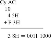
Example 1: In the addition of 45H and F3H, the result thus produced will be 38H and with Cy flag = 1, as shown below.
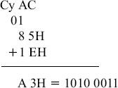
Example 2: In the addition of 85H and 1EH, the result thus produced will be A3H with Cy = 0, as shown below.
Auxiliary carry flag (Ac): Now let us consider the addition of any two 8-bit (2-hex digit) numbers, a carry may be generated when we add the LS hex digits of the two numbers. Such a carry is called intermediate carry also known as half carry, or auxiliary carry (AC). Intel prefers to call it AC. In the above Example 1, AC was not generated but in Example 2, AC is generated.
As this is only an intermediate carry, we may not be interested in storing this bit information. But 8085 microprocessor still stores this AC information in bit position 4 of the flags register. The result of execution of DAA instruction, is affected by the status of this flag. However, in our 8085 instruction set does not provide any instruction, which explicitly uses the AC flag.
Sign flag (S): The S flag is set to 1, when the result thus produced against any logical or arithmetic operations is negative, indicated by MS bit of 8-bit result being 1. It is reset to 0 otherwise if the result is positive, indicated by MS bit of 8-bit result being 0.
Thus, the value of S flag is essentially the value of the MS bit of the 8-bit result. In the above Example 1, as the 8-bit result is 38H = 0 011 1000, 0 in MSB indicates result is positive and the sign flag is reset to 0. Note that we are not considering here the 9-bit result including the carry, to decide the S flag value. In Example 2, as the 8-bit result is A3H = 1 010 0011, the MSB has become 1 that means negative and the sign flag is set to 1.
But when we shall work with unsigned numbers, then we shall simply ignore the S flag. For example, if we are treating 85H and 1EH as unsigned numbers, their sum will be the unsigned number A3H. In this case, S flag becomes 1, but we do not care for the value of the S flag. And we shall ignore it as well.
Instructions that use the S flag are quite often used in the user programs.
Parity flag (P): The P flag is set to 1, if the 8-bit result thus produced against any logical and arithmetic operation has an even number of 1's in it. If there are odd number of 1's in the 8-bit result, the P flag is reset to 0.
In our previous Example 1, as the 8-bit result 38H = 0011 1000 has three numbers of 1's, so having odd number of 1?s, the parity flag is reset to 0. On the other hand, in Example 2, as the 8-bit result A3H = 1010 0011 has four numbers of 1's (so an even number of 1?s), the parity flag is set to 1.
As the user does not really care for the number of 1's present in the result after an arithmetic operation, this flag is not of much use practically.
Zero flag (Z): The Z flag is set to 1, if after arithmetic and logical operations, the 8-bit result thus produced, is 00H. If the 8-bit result is not equal to 00H, the Z flag is reset to 0. Thus the Z flag is hoisted to indicate that the result is 0.
In previous Example 1, as the 8-bit result is 38H and is non-zero, the Z flag is reset to 0. Also in the other hand in Example 2, as the 8-bit result is A3H, the Z flag is reset to 0 here again. Instructions that use the Z flag are widely used in the user programs.

46K+ Views
