 Data Structure
 Networking
 RDBMS
RDBMS Operating System
 Java
Java MS Excel
 iOS
iOS HTML
HTML CSS
CSS Android
 Python
 C Programming
 C++
C++ C#
C# MongoDB
 MySQL
MySQL Javascript
 PHP
PHP
- Selected Reading
- UPSC IAS Exams Notes
- Developer's Best Practices
- Questions and Answers
- Effective Resume Writing
- HR Interview Questions
- Computer Glossary
- Who is Who
Cyclic Redundancy Check (CRC) in Arduino
CRC stands for Cyclic Redundancy Check (CRC). It is, in simple words, an algorithm used to detect errors in received messages. The idea is similar to parity, but this is much more robust.
If a transmitter is sending a packet to a receiver, the transmitter will calculate a CRC code based on some polynomial calculations on the packet, and append it to the packet. The receiver will perform the same calculations on the packet, and check if the generated CRC matches the CRC that came in with the packet. If the two match, there were no errors introduced in the transmission, and the packet is safe to process further. If they don't, the packet received is erroneous and should be discarded.
How exactly CRC works is beyond the scope of this article. There are libraries available for performing CRC calculations in Arduino. Here is an example. AVR also has a native CRC library.
Example
You are free to explore these libraries. However, we won't be using any of these. Instead, we'll write a function from scratch to return the 16-bit CRC for an array of bytes. The implementation is going to be Fletcher's checksum. It is quite robust, and even detects if the data is ordered incorrectly. Also, the algorithm is quite easy to implement −
uint16_t checksumCalculator(uint8_t * data, uint16_t length)
{
   uint16_t curr_crc = 0x0000;
   uint8_t sum1 = (uint8_t) curr_crc;
   uint8_t sum2 = (uint8_t) (curr_crc >> 8);
   int index;
   for(index = 0; index < length; index = index+1)
   {
      sum1 = (sum1 + data[index]) % 255;
      sum2 = (sum2 + sum1) % 255;
   }
   return (sum2 << 8) | sum1;
}
void setup() {
   // put your setup code here, to run once:
   Serial.begin(9600);
   Serial.println();
   uint8_t buf[10] = {1,2,3,4,5,6,7,8,9,0};
   uint16_t crc = checksumCalculator(buf,10);
   Serial.print("Calculated CRC is: ");Serial.println(crc, HEX);
}
void loop() {
   // put your main code here, to run repeatedly:
}
Output
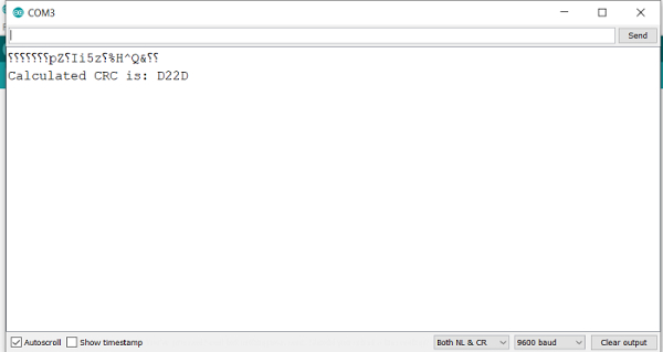
The Serial Monitor Output is

As you can see, we have used 0x0000 as the initializer. You can use a different initial value, provided both receiver and transmitter follow the same convention.
You initialize sum1 as the lower byte of the initial value, and sum2 as the higher byte. Then you keep adding successive data bytes to sum1, and sum1 values to sum2, always keeping the values less than 255 (using the modulo operator). Finally, you return a 16-bit number, with sum2 as the higher byte and sum1 as the lower byte.

