
Article Categories
- All Categories
-
 Data Structure
-
 Networking
-
 RDBMS
RDBMS
-
 Operating System
-
 Java
Java
-
 MS Excel
-
 iOS
iOS
-
 HTML
HTML
-
 CSS
CSS
-
 Android
-
 Python
-
 C Programming
-
 C++
C++
-
 C#
C#
-
 MongoDB
-
 MySQL
MySQL
-
 Javascript
-
 PHP
PHP
-
 Economics & Finance
Controlling a DC Motor with Arduino
A DC Motor is the simplest kind of motor. It has two terminals or leads. When connected with a battery the motor will rotate, and if the connections are reversed, the motor will rotate in the opposite direction. If the voltage across the terminals is reduced, the motor speed will reduce accordingly.
In this article, we will see how to interface a DC Motor with Arduino and control its speed. We won’t be looking at reversing the direction of the motor, as that will require an additional IC (an H-bridge). At the end of this article, I’ll provide links to some tutorials which explain the direction reversing of DC motors.
Alright, so let’s begin with the circuit diagram.
Circuit Diagram
A simplified version of the circuit diagram is shown below −
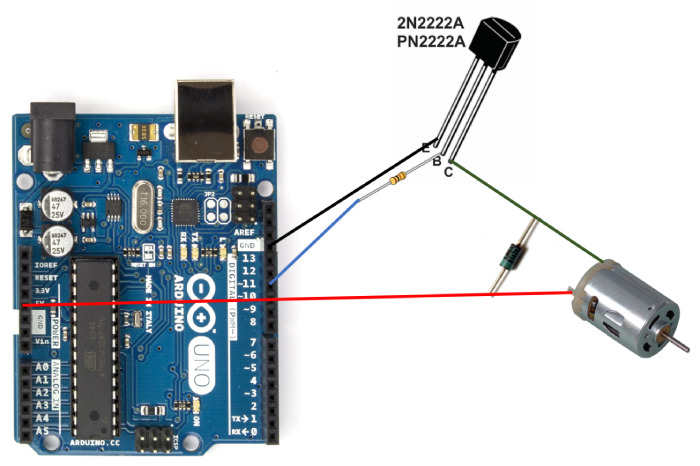
As you can see, one terminal of the motor is directly connected to +5V, while the other is connected to the Collector of the PN2222 transistor. The base of this transistor is connected to pin 11 of Arduino via a resistor, while the emitter is connected to GND. We have used a transistor because the motor may demand much higher current than what a digital pin of the Arduino can handle. Using the Arduino pin to control the base of the transistor ensures that a small current from the digital pin of the Arduino can control a much larger current of the motor. Please note that you may have to power the Arduino using a wall adapter rather than the USB if your motor draws a much larger current than what a USB can provide.
The transistor acts as a switch. When pin 11 goes to max voltage, the switch will be fully closed and the motor will experience maximum voltage difference across its terminals (Vcc and GND) and it will rotate at full speed. When the PWM duty cycle of pin 11 is reduced, the switch will be closed partially (i.e. open from some time and closed for the remaining time, depending on the duty cycle), creating lesser apparent voltage difference across the motor terminals, thereby reducing its speed. Higher the PWM duty cycle, higher will be the speed of the motor.
There is a reverse protection diode between the two terminals of the motor, with the silver (negative) end connected to the +5V line. This diode protects the Arduino and the transistor against any negative spike voltage and corresponding current from the motor that may arise when the motor is powered off.
Another variant of this circuit diagram has been taken from another TutorialsPoint tutorial and reproduced below −
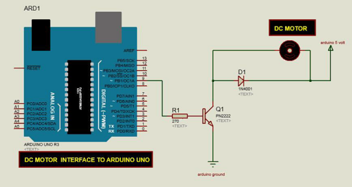
The only difference is that instead of pin 11, in the above circuit, the base of the transistor is connected to PIN 9 of Arduino. Make sure that whatever pin you connect the base to, you mention properly in your code.
Example
The code is given below −
#define basePin 11

void setup() {
   pinMode(basePin, OUTPUT);
   Serial.begin(9600);
}

void loop() {
   if (Serial.available()) {
      int user_input_speed = Serial.parseInt();
      if (user_input_speed >= 0 && user_input_speed <= 255) {
         analogWrite(basePin, user_input_speed);
      }
   }
}
As you can see, we have defined the pin connected to the base of the transistor as pin 11.
In the setup, we have defined the pin as OUTPUT and initialized Serial.
Within the loop, we take in an integer from the user, and if it is between 0 and 255, we set the PWM duty cycle of the base pin accordingly. Thus, the speed of the motor’s rotation will be proportional to the user input.
If you are interested in changing the direction of the motor’s spinning using an H-bridge, here are tutorials for the same −

821 Views
