
Article Categories
- All Categories
-
 Data Structure
-
 Networking
-
 RDBMS
RDBMS
-
 Operating System
-
 Java
Java
-
 MS Excel
-
 iOS
iOS
-
 HTML
HTML
-
 CSS
CSS
-
 Android
-
 Python
-
 C Programming
-
 C++
C++
-
 C#
C#
-
 MongoDB
-
 MySQL
MySQL
-
 Javascript
-
 PHP
PHP
-
 Economics & Finance
Rotation of stepper motor in forward and reverse directions
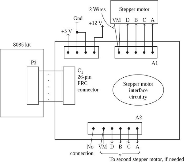
Let us consider ALS-NIFC-01, which is a stepper motor interface. Using 26-core flat cable, it is connected to ALS kit. It will be used for interfacing two stepper motors. In our current experiment, we use only one stepper motor. The motor has a step size of 1.8°. The stepper motor works on a power supply of +12V. Power supply of +5V (white wire), GND (black), and +12V (red) is provided to the interface. Note that -12V supply is not used by the interface. We shall have to make sure that the +12V supply has adequate current rating to drive the stepper motor. With the step motor interface, this is ensured by using the power supply provided.
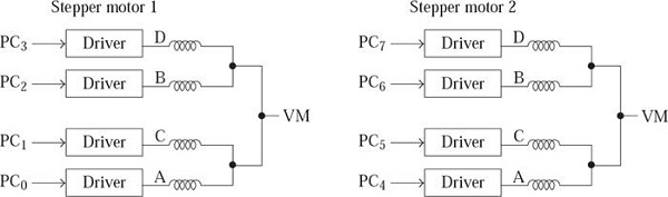
Using five-way powermate connector, the stepper motor is connected to the interface. The step motor is a two-phase, six-wire motor. The six wires are for the D, B, C, A inputs and VM connection (two wires). The five-way powermate connector is used for connection purpose. Ensure that red wire is connected to A1 on the interface. To provide DBCA inputs to one stepper motor, PC3-0 is used and for the other motor PC7-0 provides DBCA inputs, as shown in Fig. (a). Thus, the 8255 port C should be configured as an output port, while using the stepper motor interface. The physical layout of the interface is provided in Fig. (b).
It is possible to have four-step sequence with ‘one-phase ON’ scheme, as shown in the following. In this case the step size will be 1.8°.
D B C A
1 0 0 0 = 8
0 1 0 0 = 4
0 0 1 0 = 2
0 0 0 1 = 1
The 4 step sequence that we send to the stepper motor interface is 88H, 44H, 22H and 11H instead of 08H, 04H, 02H, 01H so that the step motor can be connected to any one of the two connectors provided on the interface board.
If the sequence is reversed, the rotation will also be reversed.
Let us consider a problem solution in this domain. The problem states that: The program shown here makes the step motor rotate 100 steps of 1.8 degrees each, resulting in half revolution. then, it rotates half revolution in the opposite direction. This sequence is repeated forever. To stop the operation, we have to reset the microprocessor kit.
The 8085 assembly language program is stated below for the rotation of in both forward and reverse direction.
Program
; FILE NAME STEP_MOTOR.ASM
ORG C100H
N DB 100 ; 100 steps of 1.8° = 0.5 Revolution

ORG C000H
PA EQU D8H
PB EQU D9H
PC EQU DAH
CTRL EQU DBH
DELAY EQU 04BEH

MVI A, 80H
OUT CTRL ; Configure 8255 Ports as O/P in Mode 0

BEGIN: LDA N
MOV B, A
MOV C, A ; Step Count Value in B and C Registers
; The next 7 instructions are used for Rotating by 100 Steps in One Direction

MVI A, 88H;
LOOP1:OUT PC

LXI D, FFFFH
CALL DELAY ; Generate Delay of 0.5 Secs.

RRC
DCR B
JNZ LOOP1
; The next 7 instructions are used for Rotating by 100 Steps in Opposite Direction

MVI A, 88H
LOOP2: OUT PC

LXI D, FFFFH
CALL DELAY ; Generate delay of 0.5 Secs.

RLC
DCR C
JNZ LOOP2

JMP BEGIN1

3K+ Views
