
Article Categories
- All Categories
-
 Data Structure
-
 Networking
-
 RDBMS
RDBMS
-
 Operating System
-
 Java
Java
-
 MS Excel
-
 iOS
iOS
-
 HTML
HTML
-
 CSS
CSS
-
 Android
-
 Python
-
 C Programming
-
 C++
C++
-
 C#
C#
-
 MongoDB
-
 MySQL
MySQL
-
 Javascript
-
 PHP
PHP
-
 Economics & Finance
Interfacing Stepper Motor with 8051Microcontroller
In this section, we will see how to connect a stepper motor with Intel 8051 Microcontroller. Before discussing the interfacing techniques, we will see what are the stepper motors and how they work.
Stepper Motor
Stepper motors are used to translate electrical pulses into mechanical movements. In some disk drives, dot matrix printers, and some other different places the stepper motors are used. The main advantage of using the stepper motor is the position control. Stepper motors generally have a permanent magnet shaft (rotor), and it is surrounded by a stator.
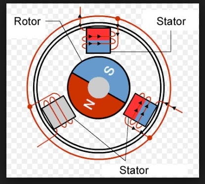
Normal motor shafts can move freely but the stepper motor shafts move in fixed repeatable increments.
Some parameters of stepper motors −
Step Angle − The step angle is the angle in which the rotor moves when one pulse is applied as an input of the stator. This parameter is used to determine the positioning of a stepper motor.
Steps per Revolution − This is the number of step angles required for a complete revolution. So the formula is 360° /Step Angle.
Steps per Second − This parameter is used to measure a number of steps covered in each second.
RPM − The RPM is the Revolution Per Minute. It measures the frequency of rotation. By this parameter, we can measure the number of rotations in one minute.
The relation between RPM, steps per revolution, and steps per second is like below:
Steps per Second = rpm x steps per revolution / 60
Interfacing Stepper Motor with 8051 Microcontroller
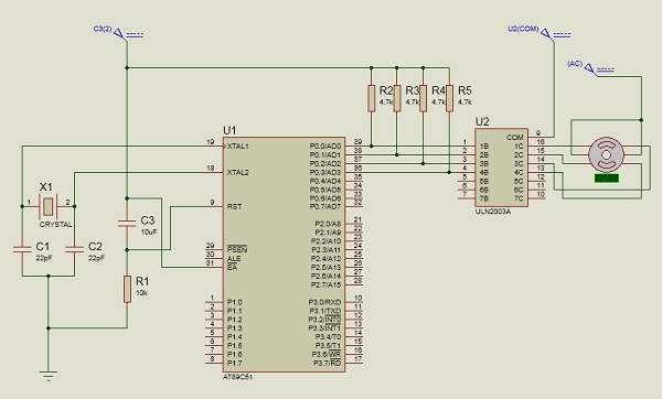
Weare using Port P0 of 8051 for connecting the stepper motor. HereULN2003 is used. This is basically a high voltage, high current Darlington transistor array. Each ULN2003 has seven NPN Darlington pairs. It can provide high voltage output with common cathode clamp diodes for switching inductive loads.
The Unipolar stepper motor works in three modes.
Wave Drive Mode − In this mode, one coil is energized at a time. So all four coils are energized one after another. This mode produces less torque than full step drive mode.
The following table is showing the sequence of input states in different windings.
| Steps |
Winding A |
Winding B |
Winding C |
Winding D |
|---|---|---|---|---|
| 1 |
1 |
0 |
0 |
0 |
| 2 |
0 |
1 |
0 |
0 |
| 3 |
0 |
0 |
1 |
0 |
| 4 |
0 |
0 |
0 |
1 |
Full Drive Mode − In this mode, two coils are energized at the same time. This mode produces more torque. Here the power consumption is also high
The following table is showing the sequence of input states in different windings.
| Steps |
Winding A |
Winding B |
Winding C |
Winding D |
|---|---|---|---|---|
| 1 |
1 |
1 |
0 |
0 |
| 2 |
0 |
1 |
1 |
0 |
| 3 |
0 |
0 |
1 |
1 |
| 4 |
1 |
0 |
0 |
1 |
Half Drive Mode − In this mode, one and two coils are energized alternately. At first, one coil is energized then two coils are energized. This is basically a combination of wave and full drive mode. It increases the angular rotation of the motor
The following table is showing the sequence of input states in different windings.
| Steps |
Winding A |
Winding B |
Winding C |
Winding D |
|---|---|---|---|---|
| 1 |
1 |
0 |
0 |
0 |
| 2 |
1 |
1 |
0 |
0 |
| 3 |
0 |
1 |
0 |
0 |
| 4 |
0 |
1 |
1 |
0 |
| 5 |
0 |
0 |
1 |
0 |
| 6 |
0 |
0 |
1 |
1 |
| 7 |
0 |
0 |
0 |
1 |
| 8 |
1 |
0 |
0 |
1 |
The circuit diagram is like below: We are using the full drive mode.
Example
#include<reg51.h>
sbit LED_pin = P2^0; //set the LED pin as P2.0
void delay(int ms){
   unsigned int i, j;
   for(i = 0; i<ms; i++){ // Outer for loop for given milliseconds value
      for(j = 0; j< 1275; j++){
         //execute in each milliseconds;
       }
   }
}
void main(){
   int rot_angle[] = {0x0C,0x06,0x03,0x09};
   int i;
   while(1){
      //infinite loop for LED blinking
      for(i = 0; i<4; i++){
         P0 = rot_angle[i];
         delay(100);
      }
   }
} 
95K+ Views
