 Data Structure
 Networking
 RDBMS
RDBMS Operating System
 Java
Java MS Excel
 iOS
iOS HTML
HTML CSS
CSS Android
 Python
 C Programming
 C++
C++ C#
C# MongoDB
 MySQL
MySQL Javascript
 PHP
PHP
- Selected Reading
- UPSC IAS Exams Notes
- Developer's Best Practices
- Questions and Answers
- Effective Resume Writing
- HR Interview Questions
- Computer Glossary
- Who is Who
Pulse Code Modulation
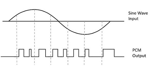
Pulse code modulation (PCM) is a technique of digitally representing analog signals. It takes samples of the amplitude of the analog signal and changes it to binary data. PCM technique is used by codecs in telephone networks to convert analog signals in local loops to digital signals in the trunks, and reverse conversion at the receivers' end.
Operations in Pulse Code Modulation
The operations in PCM technique involves operations at the transmitting end and the operations at the receiving end.
Transmitting End −
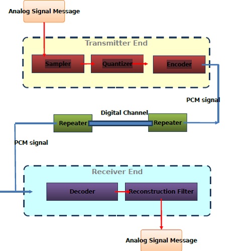
In the transmitting end, the analog signals are sampled, quantized and encoded. The codec samples the analog signal ranging from 8,000 samples per second, which is optimal sampling rate for 4KHz telephone channel. Each sample is then quantized and encoded to bits. The PCM output is then transmitted over the communication channel. There are regenerative circuits in the channel to regenerate the transmitted signal.

Receiving End−
In the receiving end, a decoder circuit demodulates the received PCM signal to produce the equivalent analog signal. This analog signal is then passed through a reconstruction filter to convert it bank to the original signal.
The whole process can be summarized through the following chart −


