- OOAD - Home
- OOAD - Object Oriented Paradigm
- OOAD - Object Oriented Model
- OOAD - Object Oriented System
- OOAD - Object Oriented Principles
- OOAD - Object Oriented Analysis
- OOAD - Dynamic Modelling
- OOAD - Functional Modelling
- OOAD - UML Analysis Model
- OOAD - UML Basic Notations
- OOAD - UML Structural Diagrams
- OOAD - UML Behavioural Diagrams
- OOAD - Object Oriented Design
- OOAD - Implementation Strategies
- OOAD - Testing & Quality Assurance
OOAD - Dynamic Modeling
The dynamic model represents the timedependent aspects of a system. It is concerned with the temporal changes in the states of the objects in a system. The main concepts are −
State, which is the situation at a particular condition during the lifetime of an object.
Transition, a change in the state
Event, an occurrence that triggers transitions
Action, an uninterrupted and atomic computation that occurs due to some event, and
Concurrency of transitions.
A state machine models the behavior of an object as it passes through a number of states in its lifetime due to some events as well as the actions occurring due to the events. A state machine is graphically represented through a state transition diagram.
States and State Transitions
State
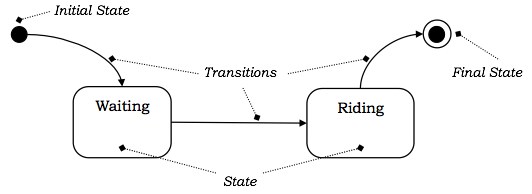
The state is an abstraction given by the values of the attributes that the object has at a particular time period. It is a situation occurring for a finite time period in the lifetime of an object, in which it fulfils certain conditions, performs certain activities, or waits for certain events to occur. In state transition diagrams, a state is represented by rounded rectangles.
Parts of a state
Name − A string differentiates one state from another. A state may not have any name.
Entry/Exit Actions − It denotes the activities performed on entering and on exiting the state.
Internal Transitions − The changes within a state that do not cause a change in the state.
Substates − States within states.
Initial and Final States
The default starting state of an object is called its initial state. The final state indicates the completion of execution of the state machine. The initial and the final states are pseudo-states, and may not have the parts of a regular state except name. In state transition diagrams, the initial state is represented by a filled black circle. The final state is represented by a filled black circle encircled within another unfilled black circle.
Transition
A transition denotes a change in the state of an object. If an object is in a certain state when an event occurs, the object may perform certain activities subject to specified conditions and change the state. In this case, a statetransition is said to have occurred. The transition gives the relationship between the first state and the new state. A transition is graphically represented by a solid directed arc from the source state to the destination state.
The five parts of a transition are −
Source State − The state affected by the transition.
Event Trigger − The occurrence due to which an object in the source state undergoes a transition if the guard condition is satisfied.
Guard Condition − A Boolean expression which if True, causes a transition on receiving the event trigger.
Action − An un-interruptible and atomic computation that occurs on the source object due to some event.
Target State − The destination state after completion of transition.
Example
Suppose a person is taking a taxi from place X to place Y. The states of the person may be: Waiting (waiting for taxi), Riding (he has got a taxi and is travelling in it), and Reached (he has reached the destination). The following figure depicts the state transition.

Events
Events are some occurrences that can trigger state transition of an object or a group of objects. Events have a location in time and space but do not have a time period associated with it. Events are generally associated with some actions.
Examples of events are mouse click, key press, an interrupt, stack overflow, etc.
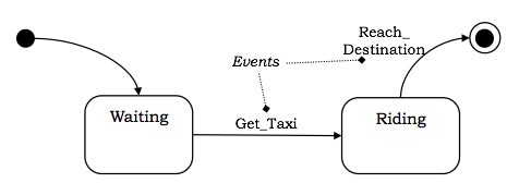
Events that trigger transitions are written alongside the arc of transition in state diagrams.
Example
Considering the example shown in the above figure, the transition from Waiting state to Riding state takes place when the person gets a taxi. Likewise, the final state is reached, when he reaches the destination. These two occurrences can be termed as events Get_Taxi and Reach_Destination. The following figure shows the events in a state machine.

External and Internal Events
External events are those events that pass from a user of the system to the objects within the system. For example, mouse click or keypress by the user are external events.
Internal events are those that pass from one object to another object within a system. For example, stack overflow, a divide error, etc.
Deferred Events
Deferred events are those which are not immediately handled by the object in the current state but are lined up in a queue so that they can be handled by the object in some other state at a later time.
Event Classes
Event class indicates a group of events with common structure and behavior. As with classes of objects, event classes may also be organized in a hierarchical structure. Event classes may have attributes associated with them, time being an implicit attribute. For example, we can consider the events of departure of a flight of an airline, which we can group into the following class −
Flight_Departs (Flight_No, From_City, To_City, Route)
Actions
Activity
Activity is an operation upon the states of an object that requires some time period. They are the ongoing executions within a system that can be interrupted. Activities are shown in activity diagrams that portray the flow from one activity to another.
Action
An action is an atomic operation that executes as a result of certain events. By atomic, it is meant that actions are un-interruptible, i.e., if an action starts executing, it runs into completion without being interrupted by any event. An action may operate upon an object on which an event has been triggered or on other objects that are visible to this object. A set of actions comprise an activity.
Entry and Exit Actions
Entry action is the action that is executed on entering a state, irrespective of the transition that led into it.
Likewise, the action that is executed while leaving a state, irrespective of the transition that led out of it, is called an exit action.
Scenario
Scenario is a description of a specified sequence of actions. It depicts the behavior of objects undergoing a specific action series. The primary scenarios depict the essential sequences and the secondary scenarios depict the alternative sequences.
Diagrams for Dynamic Modelling
There are two primary diagrams that are used for dynamic modelling −
Interaction Diagrams
Interaction diagrams describe the dynamic behavior among different objects. It comprises of a set of objects, their relationships, and the message that the objects send and receive. Thus, an interaction models the behavior of a group of interrelated objects. The two types of interaction diagrams are −
Sequence Diagram − It represents the temporal ordering of messages in a tabular manner.
Collaboration Diagram − It represents the structural organization of objects that send and receive messages through vertices and arcs.
State Transition Diagram
State transition diagrams or state machines describe the dynamic behavior of a single object. It illustrates the sequences of states that an object goes through in its lifetime, the transitions of the states, the events and conditions causing the transition and the responses due to the events.
Concurrency of Events
In a system, two types of concurrency may exist. They are −
System Concurrency
Here, concurrency is modelled in the system level. The overall system is modelled as the aggregation of state machines, where each state machine executes concurrently with others.
Concurrency within an Object
Here, an object can issue concurrent events. An object may have states that are composed of sub-states, and concurrent events may occur in each of the sub-states.
Concepts related to concurrency within an object are as follows −
Simple and Composite States
A simple state has no sub-structure. A state that has simpler states nested inside it is called a composite state. A sub-state is a state that is nested inside another state. It is generally used to reduce the complexity of a state machine. Sub-states can be nested to any number of levels.
Composite states may have either sequential sub-states or concurrent sub-states.
Sequential Sub-states
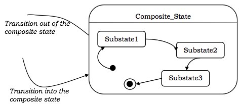
In sequential sub-states, the control of execution passes from one sub-state to another sub-state one after another in a sequential manner. There is at most one initial state and one final state in these state machines.
The following figure illustrates the concept of sequential sub-states.

Concurrent Sub-states
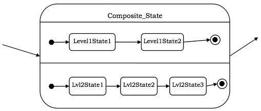
In concurrent sub-states, the sub-states execute in parallel, or in other words, each state has concurrently executing state machines within it. Each of the state machines has its own initial and final states. If one concurrent sub-state reaches its final state before the other, control waits at its final state. When all the nested state machines reach their final states, the sub-states join back to a single flow.
The following figure shows the concept of concurrent sub-states.
