- MuleSoft - Home
- MuleSoft - Introduction to Mule ESB
- MuleSoft - The Mule Project
- MuleSoft - Mule in Our Machine
- MuleSoft - Anypoint Studio
- MuleSoft - Discovering Anypoint Studio
- Creating First Mule Application
- MuleSoft - DataWeave Language
- Message Processor & Script Components
- Core Components & Their Configuration
- MuleSoft - Endpoints
- Flow Control and Transformers
- Web Services Using Anypoint Studio
- MuleSoft - Mule Error Handling
- MuleSoft - Mule exception Handling
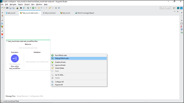
- MuleSoft - Testing with MUnit
- MuleSoft Useful Resources
- MuleSoft - Quick Guide
- MuleSoft - Useful Resources
- MuleSoft - Discussion
MuleSoft - Quick Guide
MuleSoft - Introduction to Mule ESB
ESB stands for Enterprise Service Bus which is basically a middleware tool for integrating various applications together over a bus-like infrastructure. Fundamentally, it is an architecture designed to provide a uniform means of moving work among integrated applications. In this way, with the help of ESB architecture we can connect different applications through a communication bus and enable them to communicate without depending on one another.
Implementing ESB
The main focus of ESB architecture is to decouple the systems from each other and allow them to communicate in a steady and controllable way. ESBs implementation can be done with the help of Bus and Adapter in the following way −
The concept of bus, which is achieved through a messaging server like JMS or AMQP, is used to decouple different applications from one another.
The concept of adapter, responsible for communicating with backend application and transforming data from application format to bus format, is used between applications and bus.
The data or message passing from one application to another through the bus is in a canonical format which means there would be one consistent message format.
The adapter can also perform other activities like security, monitoring, error handling and message routing management.
ESBs Guiding Principles
We can call these principles as core integration principles. They are as follows −
Orchestration − Integration of two or more services to achieve synchronization between data and process.
Transformation − Transforming data from canonical format to application specific format.
Transportation − Handling protocol negotiation between formats like FTP, HTTP, JMS, etc.
Mediation − Providing multiple interfaces to support multiple versions of a service.
Non-functional consistency − Providing mechanism for managing transactions and security also.
Need of ESB
ESB architecture enables us to integrate different applications where each application can communicate through it. Following are some guidelines on when to use ESB −
Integrating two or more applications − Use of ESB architecture is beneficial when there is a need to integrate two or more services or applications.
Integration of more applications in future − Suppose if we want to add more services or applications in future, then it can be easily done with the help of ESB architecture.
Using multiple protocols − In case if we need to use multiple protocols like HTTP, FTP, JMS etc., ESB is the right option.
Message routing − We can use ESB in case if we require message routing based on message content and other similar parameters.
Composition and consumption − ESB can be used if we need to publish services for composition and consumption.
P2P integration vs. ESB integration
With the increase in number of applications, a big question in front of developers was how to connect different applications? The situation was handled by hand-coding a connection between various application. This is called point-to-point integration.
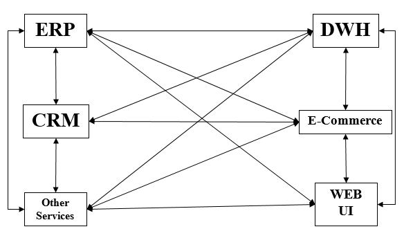
Rigidity is the most obvious drawback of point-to-point integration. The complexity increases with the increased number of connections and interfaces. The disadvantages of P-2-P integration leads us to ESB integration.
ESB is a more flexible approach to application integration. It encapsulates and exposes each application functionality as a set of discrete reusable capabilities. No application directly integrates with other, instead they integrate through an ESB as shown below −
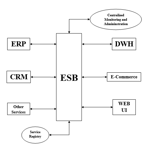
For managing the integration, ESB has the following two components −
Service Registry − Mule ESB has Service Registry/Repository where all the services exposed into the ESB are published and registered. It acts as a point of discovery from where one can consume the services and capabilities of other applications.
Centralized Administration − As the name implies, it provides a view of transactional flows of performance of interactions occurring inside the ESB.
ESB Functionality − VETRO abbreviation is generally used to summarize the functionality of ESB. It is as follows −
V(Validate) − As the name implies, it validates the schema validation. It requires a validating parser and up-to-date schema. One example is an XML document confirming to an up-to-date schema.
E(Enrich) − It adds additional data to a message. The purpose is to make message more meaningful and useful to a target service.
T(Transform) − It converts the data structure to a canonical format or from a canonical format. Examples are conversion of date/time, currency, etc.
R(Routing) − It will route the message and act as a gatekeeper of the endpoint of a service.
O(Operate) − The main job of this function is to invoke the target service or interacts with the target app. They run at the backend.
VETRO pattern provides overall flexibility to the integration and ensures that only consistent and validated data will be routed throughout the ESB.
What is Mule ESB?
Mule ESB is a lightweight and highly scalable Java-based enterprise service bus (ESB) and integration platform provided by MuleSoft. Mule ESB allows the developer to connect applications easily and quickly. Regardless of various technologies used by applications, Mule ESB enables easy integration of applications, enabling them to exchange data. Mule ESB has the following two editions −
- Community Edition
- Enterprise Edition
An advantage of Mule ESB is that we can easily upgrade from Mule ESB community to Mule ESB enterprise because both the editions are built on a common code base.
Features & Capabilities of Mule ESB
Following features are possessed by Mule ESB −
- It has simple drag-and-drop graphical design.
- Mule ESB is capable of visual data mapping and transformation.
- User can get the facility of 100s of pre-built certified connectors.
- Centralized monitoring and administration.
- It provides robust enterprise security enforcement capabilities.
- It provides the facility of API management.
- There is secure Data Gateway for cloud/on-premise connectivity.
- It provides the service registry where all the services exposed into the ESB are published and registered.
- Users can have control through a web-based management console.
- Rapid debugging can be performed using service flow analyzer.
MuleSoft - The Mule Project
The motivations behind the Mule project were −
to make things simpler for the programmers,
the need of lightweight and modular solution that could scale from an application-level messaging framework to an enterprise-wide highly distributable framework.
Mule ESB is designed as an event-driven as well as programmatic framework. It is event-driven because it is combined with unified representation of messages and can be expandable with pluggable modules. It is programmatic because programmers can easily implant some additional behaviors such as specific message processing or custom data transformation.
History
The historical perspective of Mule project is as follows −
SourceForge project
The Mule project was started as the SourceForge project in April 2003, and after 2 years its first version was released and moved to CodeHaus. Universal Message Object (UMO) API was at the core of its architecture. The idea behind UMO API was to unify the logic while keeping them isolated from the underlying transports.
Version 1.0
It was released in April 2005 containing numerous transports. The key focus of many other versions followed by it, was on debugging and adding new features.
Version 2.0 (Adoption of Spring 2)
Spring 2 as configuration and wiring framework was adopted in Mule 2 but it proved to be a major over-haul because of the lack of expressiveness of the required XML configuration. This issue was resolved when XML Schema-based configuration has been introduced in Spring 2.
Building with Maven
The biggest improvement that simplified Mule usage, both at development and deployment times, was the use of Maven. From version 1.3, it started to be constructed with Maven.
MuleSource
In 2006, MuleSource got incorporated to help support and enable the rapidly growing community using Mule in mission-critical enterprise applications. It proved to be the key milestone for Mule Project.
Competitors of Mule ESB
Following are some of the major competitors of Mule ESB −
- WSO2 ESB
- Oracle Service Bus
- WebSphere Message Broker
- Aurea CX Platform
- Fiorano ESB
- WebSphere DataPower Gateway
- Workday Business Process Framework
- Talend Enterprise Service Bus
- JBoss Enterprise Service Bus
- iWay Service Manager
Mules Core Concept
As discussed, Mule ESB is a lightweight and highly scalable Java-based enterprise service bus (ESB) and integration platform. Regardless of various technologies used by applications, Mule ESB enables easy integration of applications, enabling them to exchange data. In this section, we will discuss about Mules core concept coming into play to make such integration happen.
For this, we need to understand its architecture as well as building blocks.
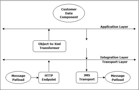
Architecture
The architecture of Mule ESB has three layers namely, Transport layer, Integration layer and Application layer as shown in the following diagram −
Generally, there are following three types of tasks that can be performed to configure and customize Mule deployment −
Service Component Development
This task involves development or re-using the existing POJOs, or Spring Beans. POJOs is a class with attributes that generates the get and set methods, cloud connectors. On the other hand, Spring Beans contains the business logic to enrich messages.
Service Orchestration
This task basically provides the service mediation that involves configuring the message processor, routers, transformers and filters.
Integration
The most important task of Mule ESB is the integration of various applications regardless of the protocols they are using. For this purpose, Mule provides transport methods that allow receiving and dispatching the messages on various protocol connectors. Mule supports many existing transport methods, or we may also use a custom transport method.
Building Blocks
Mule configuration has the following building blocks −
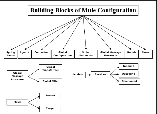
Spring beans
The main use of Spring beans is to construct service component. After constructing spring service component, we can define it through a configuration file or manually, in case you do not have configuration file.
Agents
It is basically a service created in Anypoint Studio before Mule Studio. An agent is created once you start a server and will be destroyed once you stop the server.
Connector
It is a software component configured with the parameters that are specific to protocols. It is mainly used for controlling the usage of a protocol. For example, a JMS connector is configured with a Connection and this connector will be shared among various entities in charge of actual communication.
Global Configuration
As the name implies, this building block is used to set the global properties and settings.
Global Endpoints
It can be used in Global Elements tab which can be used as many times in a flow −
Global Message Processor
As the name implies, it observes or modifies a message or message flow. Transformers and filters are the examples of Global Message Processor.
Transformers − The main job of a transformer is to convert data from one format to another. It can be defined globally and can be used in multiple flows.
Filters − It is the filter that will decide which Mule message should be processed. Filter basically specifies the conditions that must be met for a message to be processed and routed to a service.
Models
In contrast to Agents, it is a logical grouping of services which are created in studio. We have the liberty to start and stop all the services inside a specific model.
Services − Services are the one that wrap our business logic or components. It also configures Routers, Endpoints, transformers and filters specifically for that service.
Endpoints − It may be defined as an object on which services will inbound (receive) and outbound (send) messages. Services are connected through endpoints.
Flow
Message processor use flows to define a message flow between a source and a target.
Mule Message Structure
A Mule message, totally wrapped under Mule Message Object, is the data that passes through applications via Mule flows. The structure Mules message is shown in the following diagram −
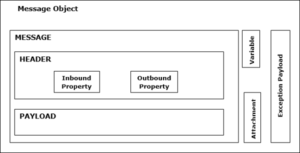
As seen in the above diagram, Mule Message consists of two main parts −
Header
It is nothing but the metadata of the message which is further represented by the following two properties −
Inbound Properties − These are the properties which are automatically set by the message source. They cannot be manipulated or set by the user. In nature, inbound properties are immutable.
Outbound Properties − These are the properties that contain metadata like an inbound property and can set during the course of flow. They can be set automatically by Mule or manually by a user. In nature, outbound properties are mutable.
Outbound properties become inbound properties when the message passes from the outbound endpoint of one flow to the inbound endpoint of a different flow via a transport.
Outbound properties remain outbound properties when the message is passed to a new flow via a flow-ref rather than a connector.
Payload
The actual business message carried by message object is called payload.
Variables
It may be defined as the user-defined metadata about a message. Basically, variables are temporary pieces of information about a message used by the application that is processing it. It is not meant to be passed along with the messages to its destination. They are of three types as given below −
Flow variables − These variables apply only to the flow in which they exist.
Session variables − These variables apply across all the flows within the same application.
Record variables − These variables apply only to records processed as part of a batch.
Attachments and Extra Payload
These are some extra metadata about message payload which is not necessarily appeared every time in message object.
MuleSoft - Mule in Our Machine
In the previous chapters, we have learnt the basics of Mule ESB. In this chapter, let us learn how to install and configure it.
Prerequisites
We need to satisfy the following prerequisites before installing Mule on our computer −
Java Development Kit (JDK)
Before installing MULE, verify that you have supported version of Java on your system. JDK 1.8.0 is recommended to successfully install Mule on your system.
Operating System
Following operating systems are supported by Mule −
- MacOS 10.11.x
- HP-UX 11iV3
- AIX 7.2
- Windows 2016 Server
- Windows 2012 R2 Server
- Windows 10
- Windows 8.1
- Solaris 11.3
- RHEL 7
- Ubuntu Server 18.04
- Linux Kernel 3.13+
Database
An application server or database is not required as the Mule Runtime runs as a standalone server. But if we need to access a data store or want to use an application server, following supported application servers or databases can be used −
- Oracle 11g
- Oracle 12c
- MySQL 5.5+
- IBM DB2 10
- PostgreSQL 9
- Derby 10
- Microsoft SQL Server 2014
System Requirements
Before installing Mule on your system, it must fulfil the following system requirements −
- At least 2 GHz CPU or 1 Virtual CPU in virtualized environments
- Minimum 1 GB RAM
- Minimum 4 GB storage
Download Mule
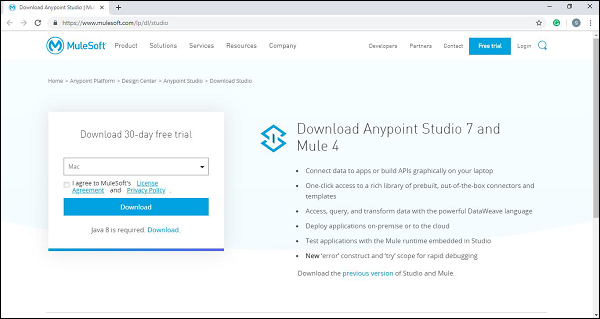
To download Mule 4 binary file, click on the link https://www.mulesoft.com/lp/dl/anypoint-mule-studio and it will lead you to the official web page of MuleSoft as follows −
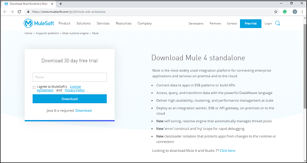
By providing the necessary details, you can get the Mule 4 binary file in Zip format.
Install and Run Mule
Now after downloading the Mule 4 binary file, unzip it and set an environment variable called MULE_HOME for the Mule directory inside the extracted folder.
For example, the environment variable, on Windows and Linux/Unix environments, can be set for version 4.1.5 in the Downloads directory as follows −
Windows Environments
$ env:MULE_HOME=C:\Downloads\mule-enterprise-standalone-4.1.5\
Unix/Linux Environments
$ export MULE_HOME=~/Downloads/mule-enterprise-standalone-4.1.5/
Now, for testing whether Mule is running in your system without any error, use the following commands −
Windows Environments
$ $MULE_HOME\bin\mule.bat
Unix/Linux Environments
$ $MULE_HOME/bin/mule
The above commands will run Mule in the foreground mode. If Mule is running, we cannot issue any other commands on the terminal. Pressing ctrl-c command in the terminal, will stop Mule.
Start Mule Services
We can start Mule as a Windows Service and as a Linux/Unix Daemon also.
Mule as a Windows Service
To run Mule as a Windows service, we need to follow the below steps −
Step 1 − First, install it with the help of following command −
$ $MULE_HOME\bin\mule.bat install
Step 2 − Once installed, we can run mule as a Windows service with the help of the following command:
$ $MULE_HOME\bin\mule.bat start
Mule as a Linux/Unix Daemon
To run Mule as a Linux/Unix Daemon, we need to follow the below steps −
Step 1 − Install it with the help of the following command −
$ $MULE_HOME/bin/mule install
Step 2 − Once installed, we can run mule as a Windows service with the help of following command −
$ $MULE_HOME/bin/mule start
Example
The following example starts Mule as a Unix Daemon −
$ $MULE_HOME/bin/mule start
MULE_HOME is set to ~/Downloads/mule-enterprise-standalone-4.1.5
MULE_BASE is set to ~/Downloads/mule-enterprise-standalone-4.1.5
Starting Mule Enterprise Edition...
Waiting for Mule Enterprise Edition.................
running: PID:87329
Deploy Mule Apps
We can deploy our Mule apps with the help of following steps −
Step 1 − First, start Mule.
Step 2 − Once Mule starts, we can deploy our Mule applications by moving our JAR package files to the apps directory in $MULE_HOME.
Stop Mule Services
We can use stop command to stop Mule. For example, the following example starts Mule as a Unix Daemon −
$ $MULE_HOME/bin/mule stop
MULE_HOME is set to /Applications/mule-enterprise-standalone-4.1.5
MULE_BASE is set to /Applications/mule-enterprise-standalone-4.1.5
Stopping Mule Enterprise Edition...
Stopped Mule Enterprise Edition.
We can also use remove command to remove the Mule Service or Daemon from our system. The following example removes Mule as a Unix Daemon −
$ $MULE_HOME/bin/mule remove
MULE_HOME is set to /Applications/mule-enterprise-standalone-4.1.5
MULE_BASE is set to /Applications/mule-enterprise-standalone-4.1.5
Detected Mac OSX:
Mule Enterprise Edition is not running.
Removing Mule Enterprise Edition daemon...
MuleSoft - Anypoint Studio
MuleSofts Anypoint Studio is a user-friendly IDE (integration development environment) used for designing and testing Mule applications. It is an Eclipse-based IDE. We can easily drag Connectors from the Mule Palette. In other words, Anypoint Studio is an Eclipse based IDE for development of flow, etc.
Prerequisites
We need to satisfy following prerequisites before installing Mule on all OS, i.e., Windows, Mac and Linux/Unix.
Java Development Kit (JDK) − Before installing Mule, verify that you have supported version of Java on your system. JDK 1.8.0 is recommended to successfully install Anypoint on your system.
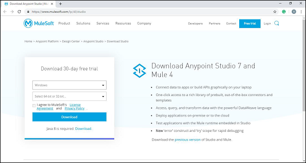
Downloading and Installing Anypoint Studio
The procedure to download and install Anypoint Studio on different operating systems may vary. Next, there are steps to be followed for downloading and installing Anypoint Studio on various operating systems −
On Windows
To download and install Anypoint Studio on Windows, we need to follow the steps below −
Step 1 − First, click on the link https://www.mulesoft.com/lp/dl/anypoint-mule-studio and choose the Windows operating system from top-down list to download the studio.
Step 2 − Now, extract it into the C:\ root folder.
Step 3 − Open the extracted Anypoint Studio.
Step 4 − For accepting the default workspace, click OK. You will get a welcome message when it loads for the first time.
Step 5 − Now, click on Get Started button to use Anypoint Studio.
On OS X
To download and install Anypoint Studio on OS X, we need to follow the steps below −
Step 1 − First, click on the link https://www.mulesoft.com/lp/dl/anypoint-mule-studio and download the studio.
Step 2 − Now, extract it. In case if you are using OS version Sierra, make sure to move the extracted app to /Applications folder before launching it.
Step 3 − Open the extracted Anypoint Studio.
Step 4 − For accepting the default workspace, click OK. You will get a welcome message when it loads for the first time.
Step 5 − Now, click on Get Started button to use Anypoint Studio.
If you are going to use custom path to your workspace, then please note that Anypoint Studio does not expand the ~ tilde used in Linux/Unix systems. Hence, it is recommended to use the absolute path while defining the workspace.
On Linux
To download and install Anypoint Studio on Linux, we need to follow the steps below −
Step 1 − First, click on the link https://www.mulesoft.com/lp/dl/anypoint-mule-studio and choose the Linux operating system from top-down list to download the studio.

Step 2 − Now, extract it.
Step 3 − Next, open the extracted Anypoint Studio.
Step 4 − For accepting the default workspace, click OK. You will get a welcome message when it loads for the first time.
Step 5 − Now, click on Get Started button to use Anypoint Studio.
If you are going to use custom path to your workspace, then please note that Anypoint Studio does not expand the ~ tilde used in Linux/Unix systems. Hence, it is recommended to use the absolute path while defining the workspace.
It is also recommended to install GTK version 2 to use complete Studio Themes in Linux.
Features of Anypoint Studio
Following are some features of Anypoint studio enhancing the productivity while building Mule applications −
It provides an instant run of Mule application inside a local runtime.
Anypoint studio gives us visual editor for configuring API definition files and Mule domains.
It has embedded unit testing framework enhancing the productivity.
Anypoint studio provides us the Built-in support to deploy to CloudHub.
It has the facility to integrate with Exchange for importing templates, examples, definitions and other resources from other Anypoint Platform organization.
MuleSoft - Discovering Anypoint Studio
Anypoint Studio editors help us design our applications, APIs, properties and configuration files. Along with designing, it also helps us to edit them. We have the Mule configuration file editor for this purpose. To open this editor, double-click on the application XML file in /src/main/mule.
To work with our application, we have the following three tabs under Mule Configuration file editor.
The Message Flow tab
This tab gives a visual representation of work flow. It basically contains a canvas that helps us check our flows visually. If you want to add Event Processors from the Mule Palette into the canvas, then just drag and drop and it will reflect in the canvas.

By clicking on an Event Processor, you can get the Mule Properties View with the attributes for the selected processor. We can also edit them.
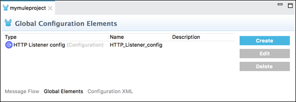
The Global Elements tab
This tab contains the global Mule configuration elements for the modules. Under this tab we can create, edit or delete configuration files.
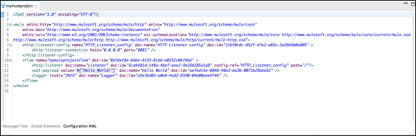
The Configuration XML tab
As the name implies, it contains the XML that defines your Mule application. All the changes you do here will reflect in the canvas as well as the properties view of event processor under the Message Flow tab.
Views
For the active editor, Anypoint studio gives us the graphical representation of our project metadata, properties with the help of views. A user can move, close as well as add views in the Mule project. Following are some default views in Anypoint studio −
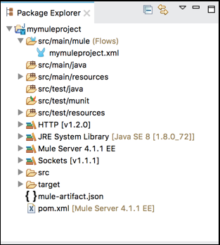
Package Explorer
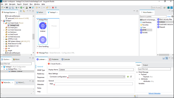
The main task of Package Explorer view is to display the project folders and files consisted in a Mule project. We can expand or contract the Mule project folder by clicking on the arrow next to it. A folder or file can be opened by double clicking it. Have a look at its screenshot −
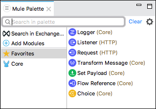
Mule Palette
Mule Palette view shows the event processors like scopes, filters, and flow control routers along with modules and their related operations. The main tasks of Mule Palette view are as follows −
- This view helps us to manage the modules and connectors in our project.
- We can also add new elements from Exchange.
Have a look at its screenshot −
Mule Properties
As the name implies, it allows us to edit the properties of the module currently selected in our canvas. Mule Properties view includes the following −
DataSense Explorer that supplies real-time information about the data structure of our payload.
Inbound and outbound properties, if available or variables.
Below is the screenshot −
Console
Whenever we create or run the Mule application, embedded Mule server displays a list of events and problems, if any, reported by Studio. Console view contains the console of that embedded Mule server. Have a look at its screenshot −
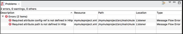
Problems View
We can encounter many issues while working on our Mule Project. All those issues are displayed in the Problems view. Below is the screenshot
Perspectives
In Anypoint Studio, it is a collection of views and editors in a specified arrangement. There are two kinds of perspectives in Anypoint Studio −
Mule Design Perspective − It is the default perspective we get in Studio.
Mule Debug Perspective − Another perspective supplied by Anypoint Studio is Mule Debug Perspective.
On the other hand, we can also create our own perspective and can add or remove any of the default views.
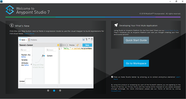
MuleSoft - Creating First Mule Application
In this chapter we are going to create our first Mule application in MuleSofts Anypoint Studio. For creating it, first we need to launch Anypoint Studio.
Launching Anypoint Studio
Click on Anypoint Studio to launch it. If you are launching it for first time, then you will see the following window −
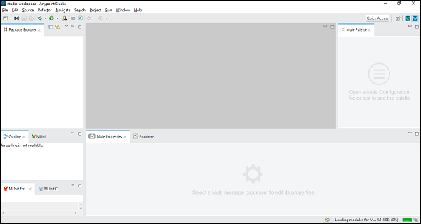
User Interface of Anypoint Studio
Once you Click on the Go to Workspace button, it will lead you to the user interface of Anypoint Studio as follows −
Steps for Creating Mule Application
In order to create your Mule application, follow the below steps −
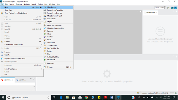
Creating New Project
The very first step for creating Mule application is to create a new project. It can be done by following the path FILE → NEW → Mule Project as shown below −
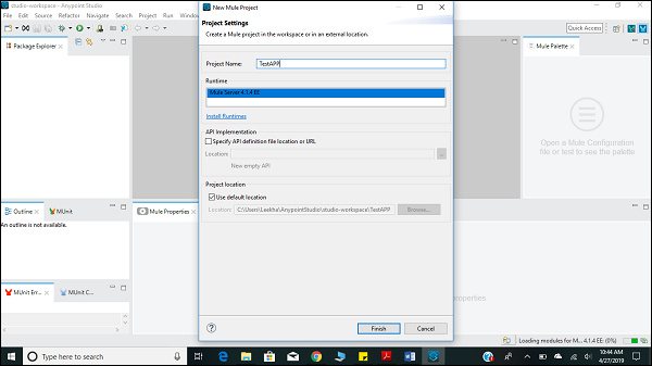
Naming the Project
After clicking on the new Mule Project, as described above, it will open a new window asking for the project name and other specifications. Give the name of the Project, TestAPP1 and then click on the finish button.
Once you click on the Finish Button, it will open the workspace built for your MuleProject namely TestAPP1. You can see all the Editors and Views described in the previous chapter.
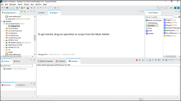
Configuring the Connector
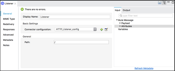
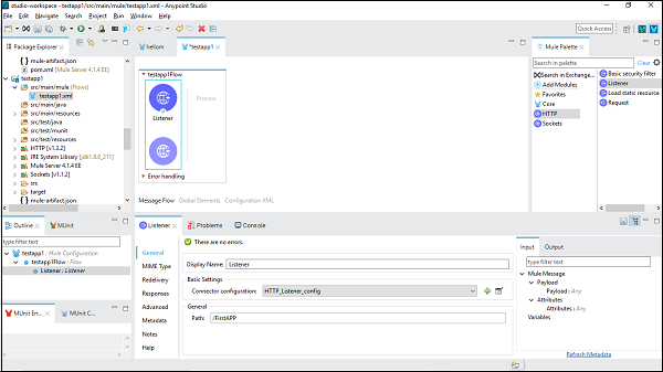
Here, we are going to build a simple Mule application for HTTP Listener. For this, we need to drag the HTTP Listener connector from Mule Palette and drop it to the workspace as shown below −

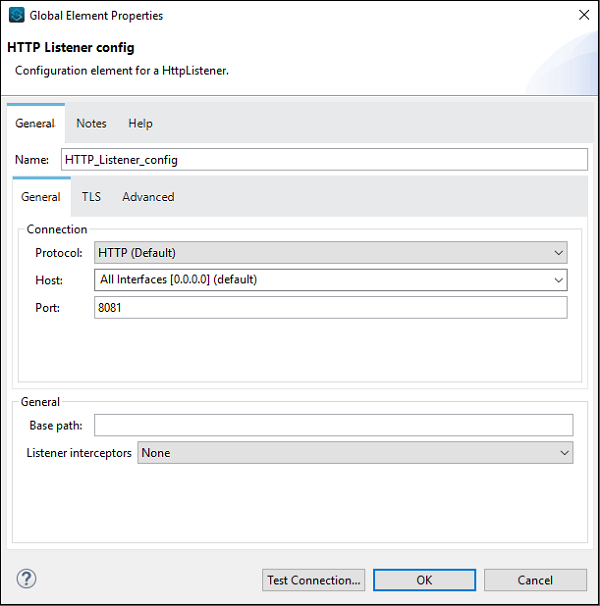
Now, we need to configure it. Click on the green color + sign after Connector configuration under Basic Settings as shown above.
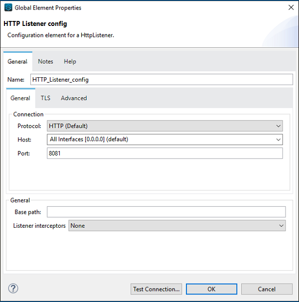
On clicking ok, it will take you back on HTTP Listener property page. Now we need to provide the path under General Tab. In this particular example, we have provided /FirstAPP as path name.

Configuring Set Payload Connector
Now, we need to take a Set Payload connector. We also need to give its value under Settings tab as follows −
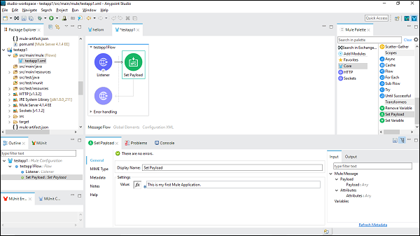
This is my first Mule Application, is the name provided in this example.
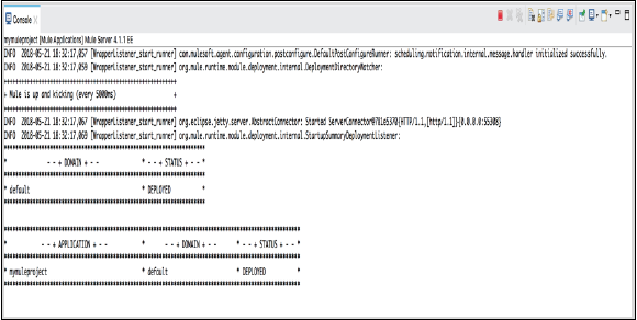
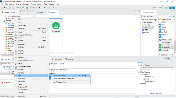
Running Mule Application
Now, save it and click Run as Mule Application as shown below −
We can check it under Console which deploys the application as follows −
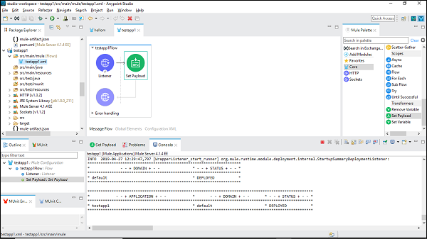
It shows that you have successfully built your first Mule Application.
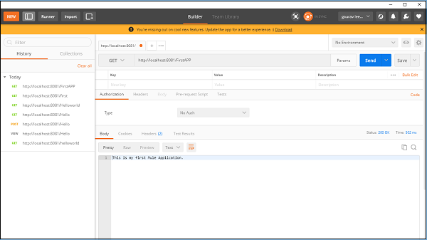
Verifying Mule Application
Now, we need to test whether our app is running or not. Go to POSTMAN, a Chrome app and enter the Url: http:/localhost:8081. It shows the message we have provided while building Mule application as shown below −
MuleSoft - DataWeave Language
DataWeave is basically a MuleSoft expression language. It is mainly used for accessing and transforming the data received through a Mule application. Mule runtime is responsible for running the script and expressions in our Mule application, DataWeave is strongly integrated with Mule runtime.
Features of DataWeave Language
Following are some important features of DataWeave language −
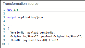
Data can be transformed from one format to another very easily. For example, we can transform application/json to application/xml. The input payload is as follows −
{
   "title": "MuleSoft",
   "author": " tutorialspoint.com ",
   "year": 2019
}
Following is the code in DataWeave for transform −
%dw 2.0
output application/xml
---
{
   order: {
      'type': 'Tutorial',
      'title': payload.title,
      'author': upper(payload.author),
      'year': payload.year
   }
}
Next, the output payload is as follows −
<?xml version = '1.0' encoding = 'UTF-8'?>
<order>
   <type>Tutorial</type>
   <title>MuleSoft</title>
   <author>tutorialspoint.com</author>
   <year>2019</year>
</order>
The transform component can be used for creating scripts that performs both simple as well as complex data transformations.
We can access and use core DataWeave functions on parts of the Mule event that we need as most of the Mule message processors support DataWeave expressions.
Prerequisites
We need to satisfy the following prerequisites before using DataWeave scripts on our computer −
Anypoint Studio 7 is required to use Dataweave scripts.
After installing Anypoint Studio, we need to set up a project with a Transform Message component in order to use DataWeave scripts.
Steps for Using DataWeave Script with Example
In order to use DataWeave scrip, we need to follow the steps below −
Step 1
First, we need to set up a new project, as we did in the previous chapter, by using File → New → Mule Project.
Step 2
Next, we need to provide the name of the project. For this example, we are giving the name, Mule_test_script.
Step 3
Now, we need to drag the Transform Message component from Mule Palette tab into canvas. It is shown as below −
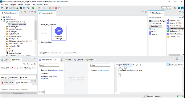
Step 4
Next, in the Transform Message component tab, click on Preview to open Preview pane. We can expand the source code area by clicking the empty rectangle next to Preview.
Step 5
Now, we can start scripting with DataWeave language.
Example
Following is the simple example of concatenating two strings into one −
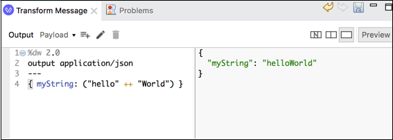
The above DataWeave script is having a key-value pair ({ myString: ("hello" ++ "World") }) which will concatenate two strings into one.
MuleSoft - Message Processor & Script Components
The scripting modules facilitate users to use scripting language in Mule. In simple words, the scripting module can exchange custom logic written in scripting language. Scripts can be used as Implementations or transformers. They can be used for expression evaluation, i.e., for controlling message routing.
Mule has the following supported scripting languages −
- Groovy
- Python
- JavaScript
- Ruby
How to Install Scripting Modules?
Actually, Anypoint Studio comes with the scripting modules. If you do not find the module in Mule Palette, then it can be added by using +Add Module. After adding, we can use the scripting module operations in our Mule application.
Implementing Example
As discussed, we need to drag and drop the module into canvas for creating workspace and use it in our application. Following is an example of it −
We already know how to configure the HTTP Listener component; hence we are going to discuss about configuring the Scripting Modules. We need to follow the steps written below to configure scripting module −
Step 1
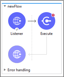
Search for the Scripting module from Mule Palette and drag the EXECUTE operation of the scripting module into your flow as shown above.
Step 2
Now, open the Execute configuration tab by double clicking on the same.
Step 3
Under the General tab, we need to provide the code in the Code text window as shown below −
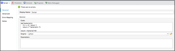
Step 4
At last, we need to choose the Engine from the execute component. The list of engines is as below −
- Groovy
- Nashorn(javaScript)
- jython(Python)
- jRuby(Ruby)
The XML of the above execution example in the Configuration XML editor is as follows −
<scripting:execute engine="jython" doc:name = "Script">
   <scripting:code>
      def factorial(n):
         if n == 0: return 1
      return n * factorial(n-1)
      result = factorial(10)
   </scripting:code>
</scripting:execute>
Message Sources
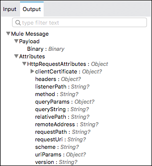
Mule 4 has a simplified model than Mule 3 message making it easier to work with data in a consistent way across connectors without overwriting information. In Mule 4 message model, each Mule event consists of two things: a message and variables associated with it.
A Mule message is having payload and its attributes, where attribute is mainly metadata such as file size.
And a variable holds the arbitrary user information such as operation result, auxiliary values, etc.
Inbound
The inbound properties in Mule 3 now becomes Attributes in Mule 4. As we know that inbound properties store additional information about the payload obtained through a message source, but this is now, in Mule 4, done with the help of attributes. Attributes have the following advantages −
With the help of attributes, we can easily see which data is available, because attributes are strongly typed.
We can easily access information contained in attributes.
Following is the example of a typical message in Mule 4 −
Outbound
The outbound properties in Mule 3 must be explicitly specified by Mule connectors and transports in order to send additional data. But in Mule 4, each of those can be set separately, using a DataWeave expression for each one of them. It does not produce any side effect in the main flow.
For example, below DataWeave expression will perform a HTTP request and generates headers and query parameters without a need to set message properties. This is shown in the below code −
<http:request path = "M_issue" config-ref="http" method = "GET">
   <http:headers>#[{'path':'input/issues-list.json'}]</http:headers>
   <http:query-params>#[{'provider':'memory-provider'}]</http:query-params>
</http:request>
Message Processor
Once Mule receives a message from a message source, the work of message processor starts. The Mule uses one or more message processors to process the message through a flow. The main task of message processor is to transform, filter, enrich and process the message as it passes through the Mule flow.
Categorization of Mule Processor
Following are the categories of Mule Processor, based on functions −
Connectors − These message processors send and receive data. They also plug data into external data sources via standard protocols or third-party APIs.
Components − These message processors are flexible in nature and perform business logic implemented in various languages like Java, JavaScript, Groovy, Python or Ruby.
Filters − They filter the messages and allow only specific messages to continue to be processed in a flow, based on specific criteria.
Routers − This message processor is used to control the flow of message to route, resequencing or split.
Scopes − hey basically wrap snippets of code for the purpose of defining fine-grained behavior within a flow.
Transformers − The role of transformers is to convert message payload type and data format to facilitate communication between systems.
Business Events − They basically capture data associated with key performance indicators.
Exception strategies − These message processors handle errors of any type that occur during message processing.
MuleSoft - Core Components & Configuration
One of the most important abilities of Mule is that it can perform routing, transforming, and processing with the components, because of which the configuration file of Mule application that combines various elements is very large in size.
Following are the types of configuration patterns provided by Mule −
- Simple service pattern
- Bridge
- Validator
- HTTP proxy
- WS proxy
Configuring the component
In Anypoint studio, we can follow the below steps to configure a component −
Step 1
We need to drag the component we wish to use in our Mule application. For example, here we use HTTP listener component as follows −
Step 2
Next, double click on the component to get the configuration window. For HTTP listener, it is shown below −
Step 3
We can configure the component as per the requirement of our project. Say for example, we did for HTTP listener component −
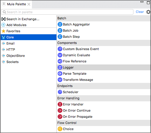
Core components are one of the important building blocks of work flow in the Mule app. The logic for processing a Mule event is provided by these core components. In Anypoint studio, to access these core components, you can click on the Core from Mule Palette as shown below −
Following are various core components and their working in Mule 4 −
Custom Business Events
This core component is used for the collection of information about flows as well as message processors that handle the business transactions in Mule app. In other words, we can use Custom Business Event component to add the following in our working flow −
- Metadata
- Key performance Indicators (KPIs)
How to add KPIs?
Following are the steps to add KPIs in our flow in Mule app −
Step 1 − Follow Mule Palette → Core → Components → Custom Business Event, to add Custom Business Event component to a working flow in your Mule app.
Step 2 − Click on the component to open it.
Step 3 − Now, we need to provide values for Display Name and Event Name.
Step 4 − To capture information from the message payload, add KPIs as follows −
Give a name (key) for the KPI (tracking: meta-data element) and a value. The name will be used in search interface of Runtime Manager.
Give a value that may be any Mule expression.
Example
Following table consists of the list of KPIs with Name and Value −
| Name | Expression/Value |
|---|---|
| Student RollNo | #[payload[RollNo]] |
| Student Name | #[payload[Name]] |
Dynamic Evaluate
This core component is used for dynamically selecting a script in Mule app. We can also use hardcore script through the Transform Message Component but using Dynamic Evaluate component is a better way. This core component works as follows −
- Firstly, it evaluates an expression that should result in another script.
- Then it evaluates that script for the final result.
In this way, it allows us to dynamically select the script rather than hardcoding it.
Example
Following is an example of selecting a script from database through an Id query parameter and storing that script in a variable named MyScript. Now, the dynamic-evaluate component will access the variable to invoke the scripts so that it can add a name variable from UName query parameter.
The XML configuration of the flow is given below −
<flow name = "DynamicE-example-flow">
   <http:listener config-ref = "HTTP_Listener_Configuration" path = "/"/>
   <db:select config-ref = "dbConfig" target = "myScript">
      <db:sql>#["SELECT script FROM SCRIPTS WHERE ID =
         $(attributes.queryParams.Id)"]
      </db:sql>
   </db:select>
   <ee:dynamic-evaluate expression = "#[vars.myScript]">
      <ee:parameters>#[{name: attributes.queryParams.UName}]</ee:parameters>
   </ee:dynamic-evaluate>
</flow>
The script can use context variables like message, payload, vars or attributes. However, if you want to add custom context variable, you need to provide a set of key-value pairs.
Configuring Dynamic Evaluate
Following table provides a way to configure Dynamic Evaluate component −
| Field | Value | Description | Example |
|---|---|---|---|
| Expression | DataWeave expression | It specifies the expression to be evaluated into the final script. | expression="#[vars.generateOrderScript]" |
| Parameters | DataWeave expression | It specifies key-value pairs. | #[{joiner: ' and ', id: payload.user.id}] |
Flow Reference Component
If you want to route the Mule event to another flow or sub-flow and back within the same Mule app, then flow reference component is the right option.
Characteristics
Following are the characteristics of this core component −
This core component allows us to treat the whole referenced flow like a single component in the current flow.
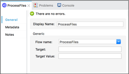
It breaks the Mule application into discrete and reusable units. For example, a flow is listing files on regular basis. It might reference another flow that processes the output of the list operation.
In this way, rather than appending the whole processing steps, we can append Flow References that points to the processing flow. The screenshot below shows that the Flow Reference Core Component is pointing towards a sub-flow named ProcessFiles.
Working
The working of Flow Ref component can be understood with the help of following diagram −
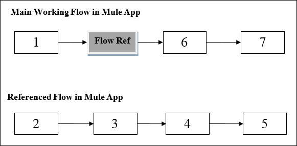
The diagram shows the processing order in Mule application when one flow references another flow in the same application. When the main working flow in Mule application triggered, the Mule event travels all through and executes the flow until the Mule event reaches Flow Reference.
After reaching Flow Reference, the Mule event executes the referenced flow from beginning to end. Once Mule event finishes executing the Ref Flow, it returns to the main flow.
Example
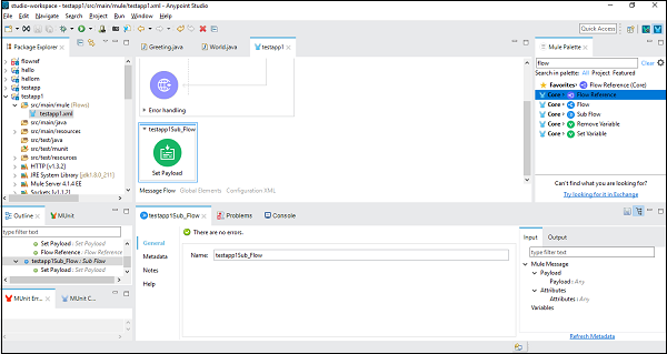
For better understanding, let us use this component in Anypoint Studio. In this example, we are taking HTTP listener to GET a message, as we did in the previous chapter. So, we can drag and drop the component and configure. But for this example, we need to add a Sub-flow component and set Payload component under that, as shown below −
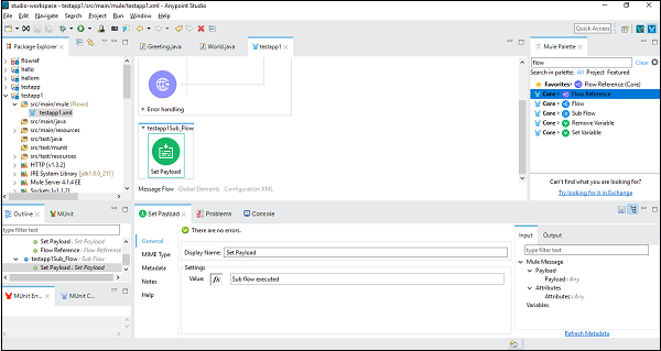
Next, we need to configure Set Payload, by double clicking on it. Here we are giving the value, Sub flow executed as shown below −
Once successfully configuring the sub-flow component, we need the Flow Reference Component to set after Set Payload of main flow, which we can drag and drop from the Mule Palette as shown below −
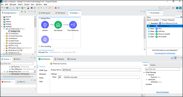
Next, while configuring the Flow Reference Component, we need to choose Flow Name under Generic tab as shown below −
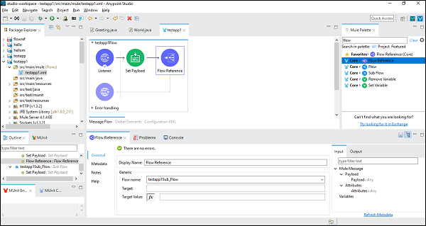
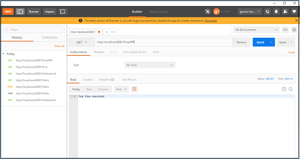
Now, save and run this application. To test this, go to POSTMAN and type http:/localhost:8181/FirstAPP in the URL bar, and you will get the message, Sub flow executed.
Logger Component
The core component called logger helps us to monitor and debug our Mule application by logging important information like error messages, status notifications, payloads, etc. In AnyPoint studio, they appear in the Console.
Advantages
Following are some advantages of Logger Component −
- We can add this core component anywhere in the working flow.
- We can configure it to log a string specified by us.
- We can configure it to the output of a DataWeave expression written by us.
- We can also configure it to any combination of strings and expressions.
Example
The example below displays the message Hello World in the Set Payload in a browser and logging the message also.
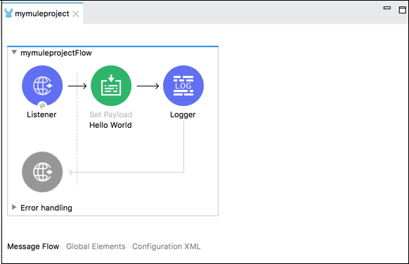
Following is the XML configuration of the flow in the above example −
<http:listener-config name = "HTTP_Listener_Configuration" host = "localhost" port = "8081"/>
<flow name = "mymuleprojectFlow">
   <http:listener config-ref="HTTP_Listener_Configuration" path="/"/>
   <set-payload value="Hello World"/>
   <logger message = "#[payload]" level = "INFO"/>
</flow>
Transfer Message Component
Transform Message Component, also called Transfer component allows us to convert the input data into a new output format.
Methods to build Transformation
We can build our transformation with the help of the following two methods −
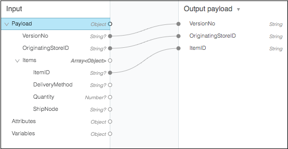
Drag-and-Drop Editor (Graphical View) − This is the first and most used method to build our transformation. In this method, we can use this components visual mapper to drag-and-drop the elements of the incoming data structure. For example, in the following diagram, two tree views show the expected metadata structures of the input and output. Lines that connect input to output field represents the mapping between two tree views.
Script View − The visual mapping of Transformation can also be represented with the help of DataWeave, a language for Mule code. We can do coding for some advanced transformations like aggregation, normalization, grouping, joining, partitioning, pivoting and filtering. The example is given below −
This core component basically accepts input and output metadata for a variable, an attribute or message payload. We can provide format-specific resources for the following −
- CSV
- Schema
- Flat file Schema
- JSON
- Object class
- Simple Type
- XML Schema
- Excel Column name and type
- Fixed Width Column name and type
MuleSoft - Endpoints
Endpoints basically include those components that trigger or initiate the processing in a working flow of Mule application. They are called Source in Anypoint Studio and Triggers in the Design Center of Mule. One important endpoint in Mule 4 is Scheduler component.
Scheduler Endpoint
This component works on time-based conditions, which means, it enables us to trigger a flow whenever a time-based condition is met. For example, a scheduler can trigger an event to start a Mule working flow every, say 10 seconds. We can also use flexible Cron expression to trigger a Scheduler Endpoint.
Important points about Scheduler
While using Scheduler event, we need to take care of some important points as given below −
Scheduler Endpoint follows the time-zone of the machine where Mule runtime is running.
Suppose if a Mule application is running in CloudHub, the Scheduler will follow the time-zone of the region in which the CloudHub worker is running.
At any given time, only one flow triggered by the Scheduler Endpoint can be active.
In Mule runtime cluster, the Scheduler Endpoint runs or triggers only on primary node.
Ways to configure a Scheduler
As discussed above, we can configure a scheduler endpoint to be triggered at a fixed interval or we can also give a Cron expression.
Parameters to configure a Scheduler (For Fixed Interval)
Following are the parameters to set a scheduler to trigger a flow at regular intervals −
Frequency − It basically describes at which frequency the Scheduler Endpoint will trigger the Mule flow. Unit of time for this can be selected from the Time Unit field. In case you do not provide any values for this, it will use the default value which is 1000. On the other side, if you provide 0 or a negative value, then also it uses the default value.
Start Delay − It is the amount of time we must wait before triggering the Mule flow for the first time once the application is started. The value of Start delay is expressed in the same unit of time as the frequency. Its default value is 0.
Time Unit − It describes the time unit for both Frequency and Start Delay. The possible values of time unit are Milliseconds, Seconds, Minute, Hours, Days. The default value is Milliseconds.
Parameters to configure a Scheduler (For Cron Expression)
Actually, Cron is a standard used for describing time and date information. In case you use the flexible Cron expression to make Scheduler trigger, the Scheduler Endpoint keeps track of every second and creates a Mule event whenever the Quartz Cron expression matches the time-date setting. With Cron expression, the event can be triggered just once or at regular intervals.
Following table gives the date-time expression of six required settings −
| Attribute | Value |
|---|---|
| Seconds | 0-59 |
| Minutes | 0-59 |
| Hours | 0-23 |
| Day of month | 1-31 |
| Month | 1-12 or JAN-DEC |
| Day of the week | 1-7 or SUN-SAT |
Some examples of Quartz Cron expressions supported by the Scheduler Endpoint are given below −
* * * * ? − means that the scheduler runs every 2 seconds of the day, every day.
0 0/5 16 ** ? − means that the scheduler runs every 5 minutes starting at 4 pm and ending at 4:55 pm, every day.
1 1 1 1, 5 * ? − means that the scheduler runs the first day of January and the first day of April, every year.
Example
The following code logs the message hi every second −
<flow name = "cronFlow" doc:id = "ae257a5d-6b4f-4006-80c8-e7c76d2f67a0">
   <doc:name = "Scheduler" doc:id = "e7b6scheduler8ccb-c6d8-4567-87af-aa7904a50359">
      <scheduling-strategy>
         <cron expression = "* * * * * ?" timeZone = "America/Los_Angeles"/>
      </scheduling-strategy>
   </scheduler>
   <logger level = "INFO" doc:name = "Logger"
      doc:id = "e2626dbb-54a9-4791-8ffa-b7c9a23e88a1" message = '"hi"'/>
</flow>
MuleSoft - Flow Control and Transformers
Flow Control (Routers)
The main task of Flow Control component is to take the input Mule event and route it to one or more separate sequences of components. It is basically routing the input Mule event to other sequence(s) of components. Therefore, it is also called as Routers. Choice and Scatter-Gather routers are the most used routers under Flow Control component.
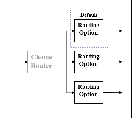
Choice Router
As the name suggests, this router applies DataWeave logic to choose one of two or more routes. As discussed earlier, each route is a separate sequence of Mule event processors. We can define choice routers as the router that dynamically routes message through a flow according to a set of DataWeave expressions used to evaluate message content.
Schematic diagram of Choice Router
The effect of using Choice router is just like adding conditional processing to a flow or an if/then/else code block in most of the programming languages. Following is the schematic diagram of a Choice Router, having three options. Among those, one is the default router.
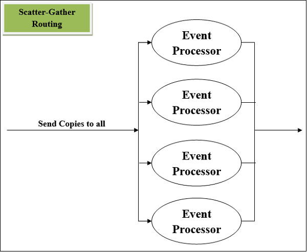
Scatter-Gather Router
Another most used routing event processor is Scatter-Gather component. As its name implies, it works on the fundamentals of scatters (copy) and Gather (Consolidates). We can understand its working with the help of following two points −
First, this router copies (Scatter) a Mule event to two or more parallel routes. The condition is that each route must be a sequence of one or more event processors which is like a sub-flow. Each route in this case will create a Mule event by using a separate thread. Every Mule event will have its own payload, attributes as well as variables.
Next, this router gathers the created Mule events from each route and then consolidates them together into a new Mule event. After this, it passes this consolidated Mule event to the next event processor. Here the condition is that the S-G router will pass a consolidated Mule event to the next event processor only when every route is completed successfully.
Schematic Diagram of Scatter-Gather Router
Following is the schematic diagram of a Scatter-Gather Router having four event processors. It executes every route in parallel and not sequentially.
Error Handling by Scatter-Gather Router
First, we must have knowledge on the kind of error that can be generated within Scatter-Gather component. Any error might be generated within event processors leading the Scatter-Gather component to throw an error of type Mule: COMPOSITE_ERROR. This error will be thrown by the S-G component only after every route either fails or completes.
To handle this error type, a try scope can be used in each route of Scatter-Gather component. If the error is successfully handled by try scope, then the route will be able to generate a Mule event, for sure.
Transformers
Suppose if we want to set or remove a part of any Mule event, Transformer component is the best choice. Transformer components are of the following types −
Remove variable transformer
As the name implies, this component takes a variable name and removes that variable from the Mule event.
Configuring removing variable transformer
The table below shows the name of fields and their description to be considered while configuring removing variable transformer −
| Sr.No | Field & Explanation |
|---|---|
| 1 |
Display Name (doc:name) We can customize this to display a unique name for this component in our Mule working flow. |
| 2 | Name (variableName) It represents the name of the variable to remove. |
Set payload transformer
With the help of set-payload component, we can update the payload, which can be a literal string or DataWeave expression, of the message. It is not recommended to use this component for complex expressions or transformations. It can be used for simple ones like selections.
The table below shows the name of fields and their description to be considered while configuring set payload transformer −
| Field | Usage | Explanation |
|---|---|---|
| Value (value) | Mandatory | The value filed is required for setting a payload. It will accept a literal string or DataWeave expression defining how to set the payload. The examples are like some string |
| Mime Type (mimeType) | Optional | Its optional but represents the mime type of the value assigned to the payload of message. The examples are like text/plain. |
| Encoding (encoding) | Optional | Its also optional but represents the encoding of the value that is assigned to the payload of message. The examples are like UTF-8. |
We can set a payload through XML configuration code −
With Static Content − Following XML configuration code will set the payload by using static content −
<set-payload value = "{ 'name' : 'Gaurav', 'Id' : '2510' }"
   mimeType = "application/json" encoding = "UTF-8"/>
With Expression Content − Following XML configuration code will set the payload by using Expression content −
<set-payload value = "#['Hi' ++ ' Today is ' ++ now()]"/>
The above example will append todays date with the message payload Hi.
Set Variable Transformer
With the help of set variable component, we can create or update a variable to store values which can be simple literal values like strings, message payloads or attribute objects, for use within the flow of Mule application. It is not recommended to use this component for complex expressions or transformations. It can be used for simple ones like selections.
Configuring set variable transformer
The table below shows the name of fields and their description to be considered while configuring set payload transformer −
| Field | Usage | Explanation |
|---|---|---|
| Variable Name (variableName) | Mandatory | It is required filed and it represents the name of the variable. While giving the name, follow the naming convention like it must contain number, characters and underscores. |
| Value (value) | Mandatory | The value filed is required for setting a variable. It will accept a literal string or DataWeave expression. |
| Mime Type (mimeType) | Optional | Its optional but represents the mime type of the variable. The examples are like text/plain. |
| Encoding (encoding) | Optional | Its also optional but represents the encoding of the variable. The examples are like ISO 10646/Unicode(UTF-8). |
Example
The example below will set the variable to the message payload −
Variable Name = msg_var
Value = payload in Design center and #[payload] in Anypoint Studio
Similarly, the example below will set the variable to the message payload −
Variable Name = msg_var
Value = attributes in Design center and #[attributes] in Anypoint Studio.
MuleSoft - Web Services Using Anypoint Studio
REST Web Service
The full form of REST is Representational State Transfer which is bound with HTTP. Hence, if you want to design an application to be used exclusively on the web, REST is the best option.
Consuming RESTful Web Services
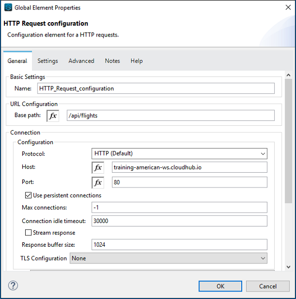
In the following example, we will be using REST component and one public RESTful service provided by Mule Soft called American Flights details. It has various details but we are going to use GET:https://training-american-ws.cloudhub.io/api/flights that will return all flight details. As discussed earlier, REST is bound with HTTP, hence we need two HTTP components one is Listener and other is Request, for this application too. Below screenshot shows the configuration for HTTP listener −
Configuring and passing arguments
The configuration for HTTP request is given below −
Now, as per our workspace flow, we have taken logger so it can be configured as below −
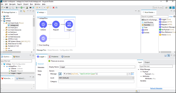
In the message tab, we write code to convert the payload into strings.
Testing the Application
Now, save and run the application and go to POSTMAN to check the final output as shown below −
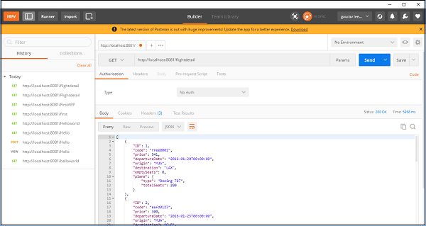
You can see it gives the flight details by using REST component.
SOAP Component
The full form of SOAP is Simple Object Access Protocol. It is basically a messaging protocol specification for exchanging information in the implementation of web services. Next, we are going to use SOAP API in Anypoint Studio to access the information using web services.
Consuming SOAP-based Web Services
For this example, we are going to use public SOAP service whose name is Country Info Service which retains the services related to country information. Its WSDL address is: http://www.oorsprong.org/websamples.countryinfo/countryinfoservice.wso?WSDL
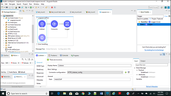
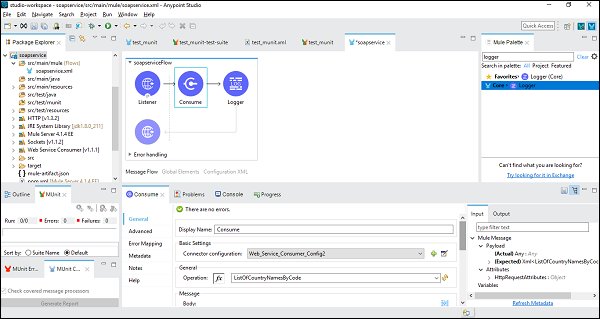
First, we need to drag SOAP consume in our canvas from Mule Palette as shown below −
Configuring and Passing Arguments
Next, we need to configure HTTP request as done in above example as given below −

Now, we also need to configure the Web Service Consumer as shown below −
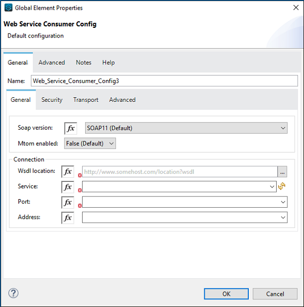
At the place of WSDL Location, we need to provide the web address of WSDL, which is provided above (for this example). Once you give the web address, Studio will search for service, Port and Address by itself. You need not provide it manually.
Transfer Response from Web Service
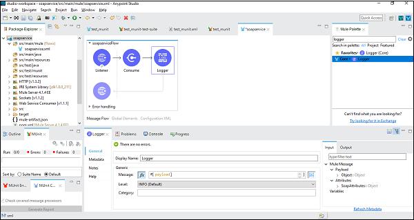
For this, we need to add a logger in the Mule flow and configure it for giving the payload as shown below −
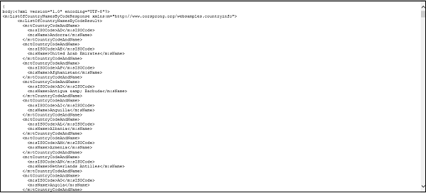
Testing the Application
Save and run the application and go to Google Chrome for checking the final output. Type http://localhist:8081/helloSOAP (for this example) and it will show the country name by code as shown in the screenshot below −
MuleSoft - Mule Error Handling
The new Mule error handling is one of the biggest and major changes done in Mule 4. The new error handing may seem complex, but it is better and more efficient. In this chapter, we are going to discuss about components of Mule error, Error types, categories of Mule error and components for handling Mule errors.
Components of Mule Error
Mule error is the result of Mule exception failure has the following components −
Description
It is an important component of Mule error which will give description about the problem. Its expression is as follows −
#[error.description]
Type
The Type component of Mule error is used to characterize the problem. It also allows routing within an error handler. Its expression is as follows −
#[error.errorType]
Cause
The Cause component of Mule error gives the underlying java throwable that causes the failure. Its expression is as follows −
#[error.cause]
Message
The Message component of Mule error shows an optional message regarding the error. Its expression is as follows −
#[error.errorMessage]
Child Errors
The Child Errors component of Mule error gives an optional collection of inner errors. These inner errors are mainly used by elements like Scatter-Gather to provide aggregated route errors. Its expression is as follows −
#[error.childErrors]
Example
In case of failure of HTTP request with a 401 status code, the Mule Errors are as follows −
Description: HTTP GET on resource http://localhost:8181/TestApp
failed: unauthorized (401)
Type: HTTP:UNAUTHORIZED
Cause: a ResponseValidatorTypedException instance
Error Message: { "message" : "Could not authorize the user." }
| Sr.NO | Error Type and Description |
|---|---|
| 1 | TRANSFORMATION This Error Type indicates an error occurred while transforming a value. The transformation is Mule Runtime internal transformation and not the DataWeave transformations. |
| 2 | EXPRESSION This kind of Error Type indicates an error occurred while evaluating an expression. |
| 3 | VALIDATION This kind of Error Type indicates a validation error occurred. |
| 4 | DUPLICATE_MESSAGE A kind of validation error which occurs when a message being processed twice. |
| 5 | REDELIVERY_EXHAUSTED This kind of Error Type occurs when maximum attempts to reprocess a message from a source has been exhausted. |
| 6 | CONNECTIVITY This Error Type indicates a problem while establishing a connection. |
| 7 | ROUTING This Error Type indicates an error occurred while routing a message. |
| 8 | SECURITY This Error Type indicates a security error occurred. For example, invalid credentials received. |
| 9 | STREAM_MAXIMUM_SIZE_EXCEEDED This Error Type occurs when the maximum size allowed for a stream exhausted. |
| 10 | TIMEOUT It indicates the timeout while processing a message. |
| 11 | UNKNOWN This Error Type indicates an unexpected error occurred. |
| 12 | SOURCE It represents the occurrence of an error in the source of the flow. |
| 13 | SOURCE_RESPONSE It represents the occurrence of an error in the source of the flow while processing a successful response. |
In the above example, you can see the message component of mule error.
Error Types
Let us understand the Error Types with the help of its characteristics −
The first characteristics of Mule Error Types is that it consists of both, a namespace and an identifier. This allows us to distinguish the types according to their domain. In the above example, the Error Type is HTTP: UNAUTHORIZED.
The second and important characteristic is that the Error Type may have a parent type. For example, the Error Type HTTP: UNAUTHORIZED has MULE:CLIENT_SECURITY as the parent which in turn also has a parent named MULE:SECURITY. This characteristic establishes the Error Type as specification of more global item.
Kinds of Error Types
Following are the categories under which all the errors fall −
ANY
The errors under this category are the errors that may occur in a Flow. They are not so severe and can be handled easily.
CRITICAL
The errors under this category are the severe errors that cannot be handled. Following is the list of Error Types under this category −
| Sr.NO | Error Type and Description |
|---|---|
| 1 | OVERLOAD This Error Type indicates an error occurred due to problem of overloading. In this case, the execution will be rejected. |
| 2 | FATAL_JVM_ERROR This kind of Error Type indicates the occurrence of a fatal error. For example, stack overflow. |
CUSTOM Error Type
The CUSTOM Error Types are the errors that are defined by us. They can be defined when mapping or when raising the errors. We must give a specific custom namespace to these Error Types for distinguishing them from the other existing Error Types within Mule application. For example, in Mule application using HTTP, we cannot use HTTP as the custom error type.
Categories of Mule Error
In broad sense, the errors in Mule can be divided into two categories namely, Messaging Errors and System Errors.
Messaging Error
This category of Mule error is related to the Mule flow. Whenever a problem occurs within a Mule flow, Mule throws a messaging error. We can set up On Error component inside the error handler component to handle these Mule errors.
System Error
System error indicates an exception occurring at the system level. If there is no Mule event, the system error is handled by a system error handler. The following kind of exceptions handle by a system error handler −
- Exception that occurs during an application start-up.
- Exception that occurs when a connection to an external system fails.
In case a system error occurs, Mule sends an error notification to the registered listeners. It also logs the error. On the other hand, Mule executes a reconnection strategy if the error was caused by a connection failure.
Handling Mule Errors
Mule has following two Error Handlers for handling the errors −
On-Error Error Handlers
The first Mule error handler is On-Error component, that defines the types of errors they can handle. As discussed earlier, we can configure On-Error components inside the scope-like Error Handler component. Each Mule flow contain only one error handler, but this error handler can contain as many On-Error scope as we needed. The steps for handling the Mule error inside the flow, with the help of On-Error component, are as follows −
First, whenever a Mule flow raises an error, the normal flow execution stops.
Next, the process will be transferred to the Error Handler Component that already have On Error component to match the error types and expressions.
At last, the Error Handler component routes the error to the first On Error scope that matches the error.
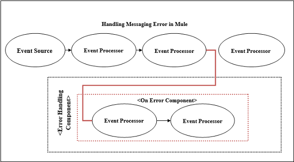
Following are the two types of On-Error components supported by Mule −
On-Error Propagate
On-Error Propagate component executes but propagates the error to the next level and breaks the owners execution. The transaction will be rolled back if it is handled by On Error Propagate component.
On-Error Continue
Like On-Error Propagate component, On-Error Continue component also executes the transaction. The only condition is, if the owner had completed the execution successfully then this component will use the result of the execution as the result of its owner. The transaction will be committed if it is handled by On-Error Continue component.
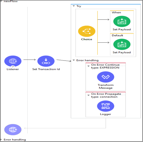
Try Scope Component
Try Scope is one of many new features available in Mule 4. It works similar to try block of JAVA in which we used to enclose the code having the possibility of being an exception, so that it can be handled without breaking the whole code.
We can wrap one or more Mule event processors in Try Scope and thereafter, try scope will catch and handle any exception thrown by these event processors. The main working of try scope revolves around its own error handling strategy which supports error handling on its inner component instead of whole flow. That is why we do not need to extract the flow into a separate flow.
Example
Following is an example of the use of try scope −
Configuring try scope for handling transactions
As we know, a transaction is a series of actions that should never be executed partially. All the operations within the scope of a transaction are executed in the same thread and if an error occurs, it should lead to a rollback or a commit. We can configure the try scope, in the following manner, so that it treats child operations as a transaction.
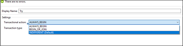
INDIFFERENT [Default] − If we choose this configuration on try block, then the child actions will not be treated as a transaction. In this case, error causes neither rollback nor commits.
ALWAYS_BEGIN − It indicates that a new transaction will be started every time the scope is executed.
BEGIN_OR_JOIN − It indicates that if the current processing of the flow has already started a transaction, join it. Otherwise, start a new one.
MuleSoft - Mule Exception handling
In case of every project, the fact about the exceptions is that they are bound to happen. That is why it is important to catch, categorize and handle exceptions so that the system/application is not left in an inconsistent state. There is a default exception strategy which is implicitly applied to all Mule applications. Rollback any pending transaction automatically is the default exception strategy.
Exceptions in Mule
Before diving deep into exceptional handling, we should understand what kind of exceptions can occur along with three basic questions that a developer must have while designing exception handlers.
Which Transport is important?
This question has ample relevance before designing exception handlers because all transports do not support transnationality.
File or HTTP does not support transactions. That is why, if an exception occurs in these cases, we must manage it manually.
Databases support transactions. While designing exception handlers in this case, we must keep in mind that database transactions can automatically rollback (if required).
In case of REST APIs, we should keep in mind that they should return the correct HTTP status codes. For example, 404 for a resource not found.
Which Message Exchange Pattern to be used?
While designing exception handlers, we must take care about Message exchange pattern. There can be synchronous (request-reply) or asynchronous (fire-forget) message pattern.
Synchronous message pattern is based on request-reply format which means this pattern will expect a response and will be blocked until a response is returned or time out happens.
Asynchronous message pattern is based on fire-forget format which means this pattern assumes that the requests will ultimately be processed.
Which type of exception is it?
Very simple rule is that you will handle the exception based on its type. It is very important to know whether the exception is caused by a system/technical issue or a business issue?
An exception occurred by system/technical issue (such as network outage) should be automatically handled by a retry mechanism.
On the other hand, an exception occurred by a business issue (such as invalid data) should not be solved by applying retry mechanism because it is not useful to retry without fixing the underlying cause.
Why to Categorize Exceptions?
As we know that all the exceptions are not same, it is very important to categorize the exceptions. At high level, the exceptions can be classified into the following two types −
Business Exceptions
The main reasons for the occurrence of business exceptions are incorrect data or incorrect process flow. These kind of exceptions are typically non-retriable in nature and hence it is not good to configure a rollback. Even applying retry mechanism would not make any sense because it is not useful to retry without fixing the underlying cause. In order to handle such exceptions, the processing should stop immediately, and the exception sent back as a response to a dead letter queue. A notification should also send to the operations.
Non-business Exceptions
The main reasons for the occurrence of non-business exceptions are system issue or technical issue. These kinds of exceptions are retriable in nature and hence its good to configure a retry mechanism in order to solve these exceptions.
Exception Handling Strategies
Mule has the following five exception handling strategies −
Default Exception Strategy
Mule implicitly applies this strategy to the Mule flows. It can handle all the exceptions in our flow, but it can also be overridden by adding a catch, Choice or Rollback exception strategy. This exception strategy will roll back any pending transactions and logs the exceptions too. An important characteristic of this exception strategy is that it will also log the exception if there is no transaction.
As being the default strategy, Mule implements this when any error occurs in the flow. We cannot configure in AnyPoint studio.
Rollback Exception Strategy
Suppose if there is no possible solution to correct the error then what to do? A solution is to use Rollback Exception Strategy which will roll back the transaction along with sending a message to the inbound connector of parent flow to reprocess the message. This strategy is also very useful when we want to reprocess a message.
Example
This strategy can be applied to banking transaction where funds are getting deposited in a checking/savings account. We can configure a rollback exception strategy here because in case if an error occurs during the transaction, this strategy rolls the message back to the beginning to the flow to reattempt processing.
Catch Exception Strategy
This strategy catches all the exceptions that are thrown within its parent flow. It overrides Mules default exception strategy by processing all the exceptions thrown by the parent flow. We can use a catch exception strategy to avoid propagating exceptions to inbound connectors and parent flows as well.
This strategy also ensures that a transaction processed by the flow is not rolled back when an exception occurs.
Example
This strategy can be applied to flight booking system in which we have a flow for processing messages from a queue. A message enricher adds a property on the message for assignment of seat and then sends the message to another queue.
Now if any error occurs in this flow, then the message will throw an exception. Here, our catch exception strategy can add a header with an appropriate message and can push that message out of the flow to the next queue.
Choice Exception Strategy
In case you want to handle the exception based on the message content, then choice exception strategy would be the best choice. The working of this exception strategy will be as follows −
- First, it catches all the exceptions thrown within the parent flow.
- Next, it checks for the message content and exception type.
- And at last, it routes the message to the appropriate exception strategy.
There would be more than one exception strategy like Catch or Rollback, defined within choice exception strategy. In case there is no strategy defined under this exception strategy, then it will route the message to the default exception strategy. It never performs any commit or rollback or consume activities.
Reference Exception Strategy
This refers to a common exception strategy that is defined in a separate configuration file. In case when a message throws an exception, this exception strategy will refer to the error handling parameters defined in a global catch, rollback or choice exception strategy. Like choice exception strategy, it never performs any commit or rollback or consume activities also.
MuleSoft - Testing with MUnit
We understand unit testing is a method by which individual units of source code can be tested to determine whether they are fit for use or not. Java programmers can use Junit framework to write test cases. Similarly, MuleSoft is also having a framework called MUnit allowing us to write automated test cases for our APIs and integrations. It is a perfect fit for continuous integration/deployment environment. One of the biggest advantages of MUnit framework is that we can integrate it with Maven and Surefire.
Features of MUnit
Following are some of the very useful features of Mule MUnit testing framework −
In MUnit framework, we can create our Mule test by using Mule code as well as Java code.
We can design and test our Mule apps and APIs, either graphically or in XML, within Anypoint Studio.
MUnit allows us to easily integrate the testing into existing CI/CD process.
It provides auto-generated tests and coverage reports; hence the manual work is minimal.
We can also use local DB/FTP/mail servers to make testing more portable through the CI process.
It allows us to enable or disable tests.
We can also extend the MUnit framework with plugins.
It allows us to verify message processor calls.
With the help of MUnit testing framework, we can disable endpoint connectors as well as flow inbound end points.
We can check error reports with Mule stack trace.
Latest Release of Mule MUnit Testing Framework
MUnit 2.1.4 is the latest release of Mule MUnit testing framework. It requires following hardware and software requirements −
- MS Windows 8+
- Apple Mac OS X 10.10+
- Linux
- Java 8
- Maven 3.3.3, 3.3.9, 3.5.4, 3.6.0
It is compatible with Mule 4.1.4 and Anypoint Studio 7.3.0.
MUnit and Anypoint Studio
As discussed, MUnit is fully integrated in Anypoint studio and we can design and test our Mule apps and APIs graphically or in XML within Anypoint studio. In other words, we can use graphical interface of Anypoint Studio to do the following −
- For creating and designing MUnit tests
- For running our tests
- For viewing test results as well as coverage report
- For debugging the tests
So, let us start discussing each task one by one.
Creating and Designing MUnit Tests
Once you start new project, it will automatically add a new folder namely src/test/munit to our project. For example, we started a new Mule project namely test_munit, you can see in the below image, it adds the above-mentioned folder under our project.
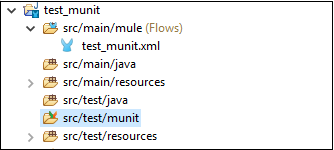
Now, once you started new project, there are two basic ways to create a new MUnit test in Anypoint Studio −
By Right-Clicking the Flow − In this method, we need to right-click the specific flow and select MUnit from the drop-down menu.
By Using the Wizard − In this method, we need to use the wizard for creating a test. It allows us to create a test for any flow in the workspace.
We are going to use Right-click the flow way to create a test for specific flow.
First, we need to create a flow in the workspace as follows −
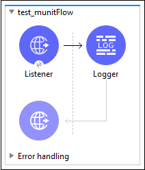
Now, right click on this flow and select MUnit to create a test for this flow, as shown below −
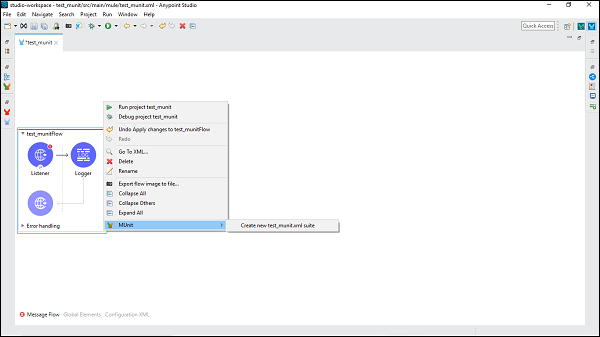
It will create a new test suite named after the XML file where the flow resides. In this case, test_munit-test-suite is the name of the new test suite as shown below −
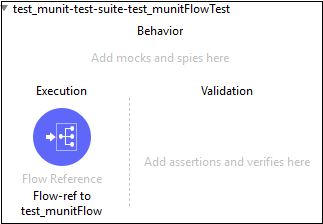
Following is the XML editor for the above message flow −
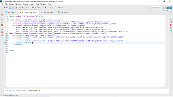
Now, we can add an MUnit message processor to the test suite by dragging it from Mule Palette.
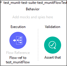
If you want to create a test via the Wizard then follow File → New → MUnit and it will lead you to the following MUnit testing suite −
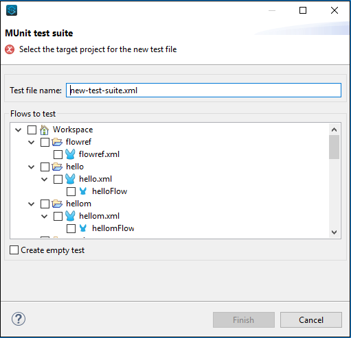
Configuring the test
In Mule 4, we have two new sections namely MUnit and MUnit Tools, collectively having all MUnit message processor. You can drag any of the message processor in your MUnit test area. It is shown in the below screenshot −
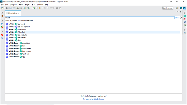
Now, if you want to edit the configuration for your suit or test in Anypoint Studio, then you need to follow the below steps −
Step 1
Go to the Package Explorer and right click on the .xml file for your suite or test. Then, select the Properties.
Step 2
Now, in the Properties window, we need to click Run/Debug Settings. After this click New.
Step 3
In the last step, click MUnit under Select Configuration Type window, and then click OK.
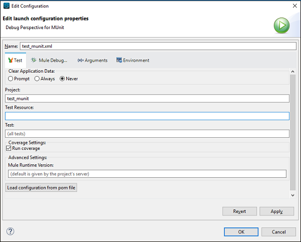
Running the Test
We can run a test suite as well as a test. First, we will see how to run a test suite.
Running a Test Suite
For running a test suite, right click on the empty part of the Mule Canvas where your test suite resides. It will open a drop-down menu. Now, click on the Run MUnit suite as shown below −
Later, we can see the output in the console.
Running a Test
To run a specific test, we need to select the specific test and right-click on that. We will get the same drop-down menu as we got while running test suite. Now, click on the Run MUnit Test option as shown below −
There after the output can be seen in the console.
Viewing and Analyzing Test Result
Anypoint studio displays the MUnit test result in the MUnit tab of the left-hand explorer pane. You can find successful tests in green color and failed tests in red one as shown below −
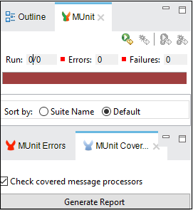
We can analyze our test result by viewing the coverage report. The main feature of Coverage Report is to provide a metric on how much of a Mule application has been successfully executed by a set of MUnit tests. MUnit coverage is basically based on the amount of MUnit message processors executed. MUnit coverage report provides metric for the following −
- Application overall coverage
- Resource coverage
- Flow coverage
To get the coverage report, we need to click on Generate Report under MUnit tab as shown below −
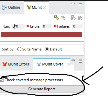
Debugging the test
We can debug a test suite as well as a test. First, we will see how to debug a test suite.
Debugging a Test Suite
For debugging a test suite, right click on the empty part of the Mule Canvas where your test suite resides. It will open a drop-down menu. Now, click on the Debug MUnit Suite as shown in the below image −
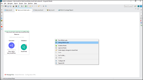
Then, we can see the output in the console.
Debugging a Test
To debug a specific test, we need to select the specific test and right-click on that. We will get the same drop-down menu as we got while debugging test suite. Now, click on the Debug MUnit Test option. It is shown in the below screen shot.