
- Microprocessor - Home
- Microprocessor Overview
- Microprocessor Classification
- Microprocessor Evolution
- Microprocessor Components
- Microprocessor Characteristics
- Microprocessor Functions
- Microprocessor Pros & Cons
- Microprocessor Application
- Microcontrollers Types
- Microcontrollers Pros & Cons
- 8085 Microprocessor Architecture
- 8085 Microprocessor Pin Configuration
- Addressing Modes & Interrupts
- 8085 Microprocessor Instruction Sets
- 8085 Microprocessor Features
- Externally Initiated Operations
- 8086 Microprocessor
- 8086 Microprocessor Overview
- Functional Units
- Pin Configuration
- Instruction Sets
- 8086 Microprocessor Interrupts
- 8086 Microprocessor Addressing Modes
- 8086 Microprocessor Features
- Memory Segmentation
- Auxiliary Carry Flag
- Maximum and Minimum Mode Configurations
- Multiprocessor Configuration
- Configuration Overview
- 8087 Numeric Data Processor
- I/O Interfacing
- I/O Interfacing Overview
- 8279 Programmable Keyboard
- 8257 DMA Controller
- Serial vs Parallel Communication
- Serial Communications Interface
- Parallel Communication Interface
- 8051 Microcontrollers
- Microcontrollers Overview
- 8051 Microcontrollers Architecture
- 8051 Pin Description
- 8051 Input Output Ports
- 8051 Microcontrollers Interrupts
- Instruction Sets
- Logical Instructions in AVR
- Conditional Branch Instructions AVR
- Arithmetic Instructions in AVR
- External Memory Interfacing
- Time Delay in AVR
- 8051 vs PIC Microcontroller
- Peripheral Devices
- Peripheral Devices
- Programmable Peripheral Interface
- Intel 8255A Pin Description
- Programmable Interval Timer
- 8253/54 Operational Modes
- Interfacing Devices
- Applications and Furture Trends
- Microcontrollers - Application
- Microprocessors and Microcontrollers in IoT
- Microcontrollers in Automotive Systems
- Microcontrollers - Low-Power
- Artificial Intelligence Processors
- Microprocessor Useful Resources
- Microprocessor - Quick Guide
- Microprocessor - Useful Resources
- Microprocessor - Discussion
8279 - Programmable Keyboard
8279 programmable keyboard/display controller is designed by Intel that interfaces a keyboard with the CPU. The keyboard first scans the keyboard and identifies if any key has been pressed. It then sends their relative response of the pressed key to the CPU and vice-a-versa.
How Many Ways the Keyboard is Interfaced with the CPU?
The Keyboard can be interfaced either in the interrupt or the polled mode. In the Interrupt mode, the processor is requested service only if any key is pressed, otherwise the CPU will continue with its main task.
In the Polled mode, the CPU periodically reads an internal flag of 8279 to check whether any key is pressed or not with key pressure.
How Does 8279 Keyboard Work?
The keyboard consists of maximum 64 keys, which are interfaced with the CPU by using the key-codes. These key-codes are de-bounced and stored in an 8-byte FIFORAM, which can be accessed by the CPU. If more than 8 characters are entered in the FIFO, then it means more than eight keys are pressed at a time. This is when the overrun status is set.
If a FIFO contains a valid key entry, then the CPU is interrupted in an interrupt mode else the CPU checks the status in polling to read the entry. Once the CPU reads a key entry, then FIFO is updated, and the key entry is pushed out of the FIFO to generate space for new entries.
Architecture and Description
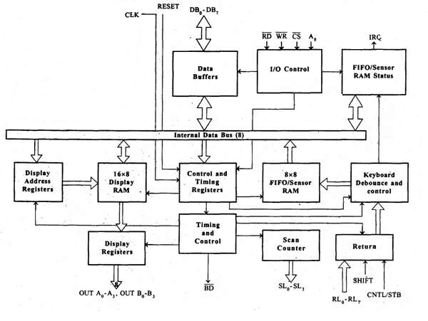
I/O Control and Data Buffer
This unit controls the flow of data through the microprocessor. It is enabled only when D is low. Its data buffer interfaces the external bus of the system with the internal bus of the microprocessor. The pins A0, RD, and WR are used for command, status or data read/write operations.
Control and Timing Register and Timing Control
This unit contains registers to store the keyboard, display modes, and other operations as programmed by the CPU. The timing and control unit handles the timings for the operation of the circuit.
Scan Counter
It has two modes i.e. Encoded mode and Decoded mode. In the encoded mode, the counter provides the binary count that is to be externally decoded to provide the scan lines for the keyboard and display.
In the decoded scan mode, the counter internally decodes the least significant 2 bits and provides a decoded 1 out of 4 scan on SL0-SL3.
Return Buffers, Keyboard Debounce, and Control
This unit first scans the key closure row-wise, if found then the keyboard debounce unit debounces the key entry. In case, the same key is detected, then the code of that key is directly transferred to the sensor RAM along with SHIFT & CONTROL key status.
FIFO/Sensor RAM and Status Logic
This unit acts as 8-byte first-in-first-out (FIFO) RAM where the key code of every pressed key is entered into the RAM as per their sequence. The status logic generates an interrupt request after each FIFO read operation till the FIFO gets empty.
In the scanned sensor matrix mode, this unit acts as sensor RAM where its each row is loaded with the status of their corresponding row of sensors into the matrix. When the sensor changes its state, the IRQ line changes to high and interrupts the CPU.
Display Address Registers and Display RAM
This unit consists of display address registers which holds the addresses of the word currently read/written by the CPU to/from the display RAM.
8279 Pin Description
The following figure shows the pin diagram of 8279 −
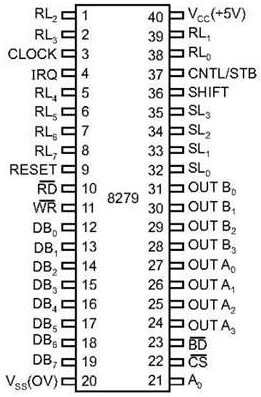
Data Bus Lines, DB0 - DB7
These are 8 bidirectional data bus lines used to transfer the data to/from the CPU.
CLK
The clock input is used to generate internal timings required by the microprocessor.
RESET
As the name suggests this pin is used to reset the microprocessor.
CS Chip Select
When this pin is set to low, it allows read/write operations, else this pin should be set to high.
A0
This pin indicates the transfer of command/status information. When it is low, it indicates the transfer of data.
RD, WR
This Read/Write pin enables the data buffer to send/receive data over the data bus.
IRQ
This interrupt output line goes high when there is data in the FIFO sensor RAM. The interrupt line goes low with each FIFO RAM read operation. However, if the FIFO RAM further contains any key-code entry to be read by the CPU, this pin again goes high to generate an interrupt to the CPU.
Vss, Vcc
These are the ground and power supply lines of the microprocessor.
SL0 SL3
These are the scan lines used to scan the keyboard matrix and display the digits. These lines can be programmed as encoded or decoded, using the mode control register.
RL0 RL7
These are the Return Lines which are connected to one terminal of keys, while the other terminal of the keys is connected to the decoded scan lines. These lines are set to 0 when any key is pressed.
SHIFT
The Shift input line status is stored along with every key code in FIFO in the scanned keyboard mode. Till it is pulled low with a key closure, it is pulled up internally to keep it high
CNTL/STB - CONTROL/STROBED I/P Mode
In the keyboard mode, this line is used as a control input and stored in FIFO on a key closure. The line is a strobe line that enters the data into FIFO RAM, in the strobed input mode. It has an internal pull up. The line is pulled down with a key closure.
BD
It stands for blank display. It is used to blank the display during digit switching.
OUTA0 OUTA3 and OUTB0 OUTB3
These are the output ports for two 16x4 or one 16x8 internal display refresh registers. The data from these lines is synchronized with the scan lines to scan the display and the keyboard.
Operational Modes of 8279
There are two modes of operation on 8279 − Input Mode and Output Mode.
Input Mode
This mode deals with the input given by the keyboard and this mode is further classified into 3 modes.
Scanned Keyboard Mode − In this mode, the key matrix can be interfaced using either encoded or decoded scans. In the encoded scan, an 8×8 keyboard or in the decoded scan, a 4×8 keyboard can be interfaced. The code of key pressed with SHIFT and CONTROL status is stored into the FIFO RAM.
Scanned Sensor Matrix − In this mode, a sensor array can be interfaced with the processor using either encoder or decoder scans. In the encoder scan, 8×8 sensor matrix or with decoder scan 4×8 sensor matrix can be interfaced.
Strobed Input − In this mode, when the control line is set to 0, the data on the return lines is stored in the FIFO byte by byte.
Output Mode
This mode deals with display-related operations. This mode is further classified into two output modes.
Display Scan − This mode allows 8/16 character multiplexed displays to be organized as dual 4-bit/single 8-bit display units.
Display Entry − This mode allows the data to be entered for display either from the right side/left side.
