- FTTH - Home
- FTTH - Introduction
- FTTH - PON
- FTTH - GPON
- FTTH - EPON
- FTTH - XPON Evaluation
- FTTH - Optical Distribution Network
- FTTH - Interview Questions
FTTH - Quick Guide
FTTH - Introduction
For the access of network technologies, there are normally two ways i.e. Fixed and the second is the Wireless way. In this tutorial, we will discuss the Fixed method, technically called as the FTTH Technology.
What is FTTH?
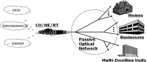
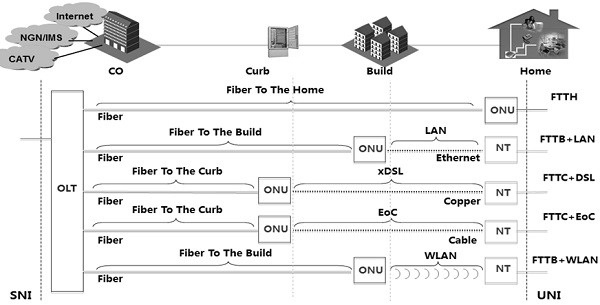
Fiber to the Home or simply FTTH is a technology that uses optical fiber directly from the central point to the residential premises (as shown in the following image). It provides uninterrupted high-speed internet service. Here, H includes both home and small business.
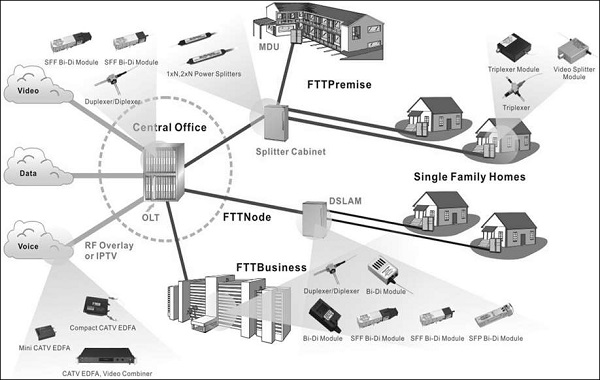
FTTH is the ultimate fiber access solution where each subscriber is connected to an optical fiber. The deployment options discussed in this tutorial are based on a complete optical fiber path from the Optical Line Termination (OLT) right to the subscriber premises.
This choice facilitates high bandwidth services and content to each customer and ensures maximum bandwidth for future demands of new services. Therefore, Hybrid options involving part fiber and part copper infrastructure networks are not included.
As an access to the home over fiber, Fiber to The Home (FTTH) scenario is mainly for the single family unit (SFU), providing a comparatively small number of ports, including the following types POTS, 10/100/1000 BASE-T, and RF (18dBmV).
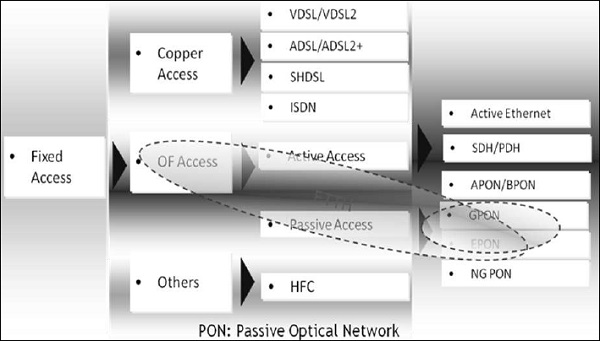
Optical Fiber Method can be deployed in two ways: Active Method and Passive Method. The current mass FTTH deployment is based on the passive method. Hence, lets discuss the Passive Method in detail.
Passive Method − The two typical technologies used in this method are Ethernet Passive Optical Network (EPON) & Gigabit-capable Passive Optical Networks (GPON). Refer the following image.
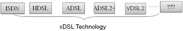
Very high bit rate digital subscriber loop (VDSL) supports a maximum bit rate of 55 bps. VDSL2 has better QoS and better SNR.
ADSL (asymmetric digital subscriber line) supports a maximum bit rate of 8Mbps, however ADSL2 can go up to 12Mbps.
SHDSL stands for symmetric high bit rate digital subscriber line. The larger the diameter of the telephone, the longer the distance it could reach. The transmission rate depends on the diameter of the telephone wire.
Integrated service digital network (ISDN) is based on circuit-switched network.
Why FTTH?
Fiber offers a number of advantages over the previous technologies (Copper). The most important ones are as follows −
- Enormous information carrying capacity
- Easily upgradeable
- Easy to install
- Allows fully symmetric services
- Reduces operations and maintenance costs
- Covers very long distances
- Strong, flexible, and reliable
- Allows small diameter and lightweight cables
- Safe and secure
- Immune to electromagnetic interference (EMI)
- Lower cost
The following table lists the advanced services that can be provided through FTTH along with their bandwidth.
| Services | Bandwidth |
|---|---|
| Data Download | 10 Mbps |
| VoIP and video-conference | 1 Mbps |
| Music on demand, multimedia contents | 2 Mbps |
| On-line Gaming | 1 Mbps |
| SD Digital TV | 3 Mbps |
| HD Digital TV | 8 Mbps |
| Additional TV channels | 16 Mbps |
FTTH vs xDSL
The following table shows a typical comparison between FTTH and xDSL devices in terms of bandwidth and distance (maximum reach) −
| Transport | ADSL | ADSL2 | ADSL2+ | VDSL | VDSL2 | FTTH PON |
|---|---|---|---|---|---|---|
| Max bandwidth | D:8M | 12M | 24M | 55M | 100M | 100+ |
| U:1M | 3.5M | 1M | 19M | 100M | 100+ | |
| Distance | 3-5KM | <=1.3KM | <=100KM | |||
Distance affects the performance of xDSL profoundly.
Distance is not a problem for FTTH, as the maximum reach is more than 20 kms.
FTTH supports all the available services.
Distance and Bandwidth
The following points explain the distance and bandwidth parameters −
- ISDN − 2B + D = 2 × 64 + 16 = 144 Kbps
- HDSDN − American standard 0.51mm, 2M max 5km.
- ADSL − 3-5 km 8 Mbps
- ADSL2 − 3-5 km 12 Mbps
- ADSL2+ − 3-5 km 24 Mbps
- VDSL − ≤ 1.3 km, 55 Mbps; VDSL2 upstream/downstream 100 Mbps
FTTH Terminologies
Let us now discuss in brief about the terminologies normally associated with FTTH.
Differential Fiber Distance
An OLT is connected to several ONU/ONTs. The differential fiber distance is the difference in the distance between the nearest and the farthest ONU/ONT from the OLT. In GPON, the maximum differential fiber distance is 20 kms. This affects the size of the ranging window and it is in accordance with ITU-T G.983.1.
Logical Reach
Logical reach is defined as the maximum distance that can be covered for a particular transmission system, regardless of the optical budget. Since, Logical reach is the maximum distance between ONU/ONT and OLT except for the limitation of the physical layer - In GPON, the maximum logical reach is defined as 60 kms.
Mean Signal Transfer Delay
The mean signal transfer delay is the average of the upstream and downstream delay values between reference points. This value is determined by measuring round-trip delay and then dividing by 2. GPON must accommodate services that require a maximum mean signal transfer delay of 1.5 Ms. Specifically, GPON system must have a maximum mean signal transfer delay time of less than1.5 Ms between T-V reference points.
Optical Access Network (OAN)
The Optical Access Network is an access network towards the network side, it is also known as SNI (Service Network Interface). Up-link ports of OLT connects with L2 Switch Ring of access network. All other in-between components such as ODF/FDMS connected towards SNI comes under the Optical Access Network.
Optical Distribution Network (ODN)
In a PON Technology towards downstream side, all passive components from the PON Port of OLT to the PON Port of ONT come under Optical Distribution Network. Normally, Splitter and ODF/FDMS come under this category.
Optical Line Termination (OLT)
A Central Office (CO) equipment provides PON with the various network interfaces. One OLT serves multiple ONTs through PON Downstream transmission, i.e., from OLT to ONT is usually TDM. Upstream traffic, i.e., from ONT to OLT is usually TDMA. PON system may be either symmetrical or asymmetrical.
Optical Network Termination (ONT)/ Optical Network Unit (ONU)
An Optical Network Termination is a Customer Premises Equipment that provides user interfaces to the customer.
Physical Reach
Physical reach is defined as the maximum physical distance that can be achieved for a particular transmission system. Physical reach is the maximum physical distance between the ONU/ONT and the OLT. In GPON, two options are defined for the physical reach: 10 km and 20 km.
Service
Service is defined as a network service required by the operators. Service is described by a name that is clearly recognized by everyone, regardless of whether it is a frame structure name or a general name.
Bit Rate
GPON aims at transmission speeds greater than or equal to 1.2 Gbps. Accordingly, GPON identifies two transmission speed combinations as follows −
- 1.2 Gbps up, 2.4 Gbps down
- 2.4 Gbps up, 2.4 Gbps down
The most important bit rate is 1.2 Gbps upstream and 2.4 Gbps downstream, constituting nearly all of the deployed and planned deployment of the GPON systems.
Split Ratio
Larger the split ratio is for GPON, the more economical it is from cost perspective. However, a larger split ratio implies greater optical power and bandwidth splitting, which creates the need for an increased power budget to support the physical reach.
Split ratios of up to 1:64 are realistic for the physical layer, given current technology. However, anticipating the continued evolution of optical modules, the TC layer must consider split ratios up to 1:128.
Data Rates
| PON | DS (Mbps) | US (Mbps) |
|---|---|---|
| BPON | 155.52 | 155.52 |
| Amd 1 | 622.08 | 155.52 |
| 622.08 | 622.08 | |
| Amd 2 | 1244.16 | 155.52 |
| 1244.16 | 622.08 | |
| GPON | 1244.16 | 155.52 |
| 1244.16 | 622.08 | |
| 1244.16 | 1244.16 | |
| 2488.32 | 155.52 | |
| 2488.32 | 622.08 | |
| 2488.32 | 1244.16 | |
| 2488.32 | 2488.32 | |
| EPON | 1250 | 1250 |
| 10GEPON+ | 10312.5 | 10312.5 |
FTTH - PON
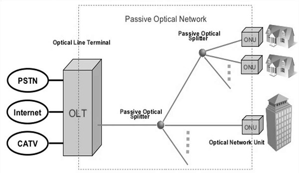
PON is Passive Optical Network featured with one-to-multiple-point architecture. As shown in the following image, it comprises of Optical Line Terminal (OLT), Optical Network Unit and Passive Optical Splitter.
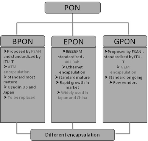
History of PON
The first Passive Optical Network (PON) activity was initiated by the FSAN group in the mid- 1990s. The initial standard covered 155 Mbps transmission based on ATM known as the APON/BPON standard. Later on, the standard enhanced to cover 622 Mbps.
In 2001, the IEEE started the development of an Ethernet based standard known as EPON.
In 2001, the FSAN group started the development of a gigabit speed standard, i.e., GPON, to be ratified by the ITU-T.
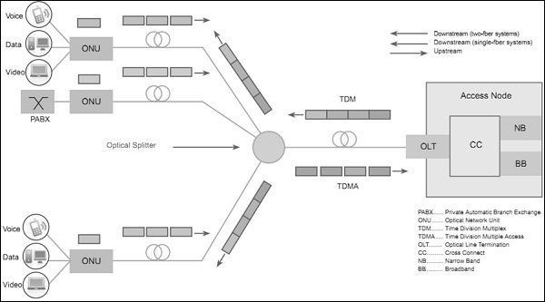
PON Network Architecture
The following illustration shows the network architecture of PON −
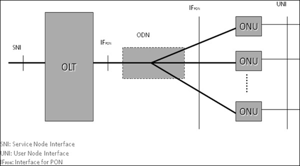
Where,
SNI − Service Node Interface
IFPON − Interface for PON
UNI − User Node Interface
As shown in the above illustration, the ODN may be configured with one or multiple splitters with several cascades.
PON Multiplexing
PON uses WDM to realize bi-directional transport on a single fiber (see the illustration given below) −
In order to distinguish the signals in two different directions, two multiplexing technologies are adopted, which are −
TDM
TDMA
Let us discuss them in detail −
Time Division Multiplexing (TDM) for downstream − It is a technique of transmitting and receiving separate signals over a common signal path. For this, it uses synchronized switches at each end of the transmission line; resultantly, each signal appears on the line only a fraction of time in an alternating pattern.
Time Division Multiple Access () for upstream − This technique facilitates many users to share the same frequency channel by dividing the signal into different time slots.
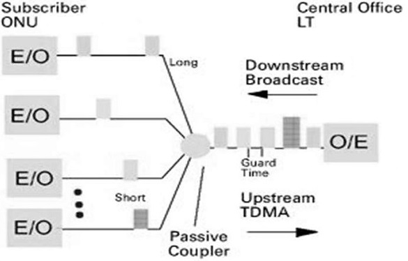
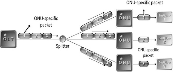
PON: Downstream
Broadcasting mode − Downstream data is broadcasted to all ONUs. But, at the ONU, only the specific packet is processed, and the rest packets are discarded.
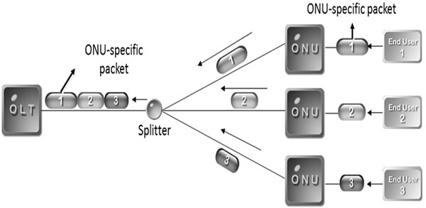
PON: Upstream (TDMA mode)
The following illustration depicts the TDMA mode.
The following illustration shows both the technologies together −
PON Terminologies
Following are the PON terminologies −
ODN (Optical Distribution Network) − An ODN realizes the optical transmission from the OLT towards the users and vice versa. It utilizes passive optical components.
OLT (Optical Line Termination) − An OLT is the service provider endpoint of a PON and is placed in a CO or head end.
ONT/ONU (Optical Network Termination) − An ONT is a device that terminates the PON and presents native service interfaces to the user. An ONT is typically located on the customers premises.
PON Access Network
Passive Optical Network (PON) is essentially a cost effective optical fiber based access system that provides triple plays (voice, video, & data) services to both the business and the residential customers. Besides, the simple topology shown in the following illustration, PON can work in other topologies. For example Bus or linear, distributed splitting, etc.
The different types of topology that are used, depends on the customer distribution profile.
An ONT can be connected to PON in any fashion as long as −
Optical budget from ONT to OLT & vice-versa is met.
Specification of maximum differential distance between different ONTs is met.
Fiber length from ONT to OLT is within allowable range.
Limit of maximum number of ONTs that the PON system can support is not exceeded.
Passive Modules in PON
Following are the Passive modules in the PON system −
- WDM Coupler
- 1 × N Splitter
- Optical fiber and cable
- Connector
- ODF/Cabinet/Subrack
Active Modules in PON
Following are the active modules in the PON system −
In OLT −
- Laser transmitter (1490-nm)
- Laser receivers (1310-nm)
- For CATV application
- Laser amplifier (1550-nm)
- EDFA for amplifying video signal
In ONU −
- X`Power/Battery for ONU
- Laser transmitter (1310-nm)
- Laser receivers (1490-nm)
- Receivers for CATV signal (1550-nm)
In the next chapter, we will understand what Gigabit Passive Optical Networks are.
FTTH - GPON
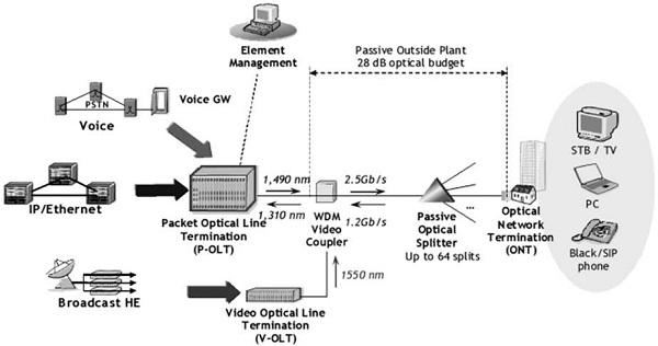
GPON (Gigabit Passive Optical Networks) is an Optical System for the Access Networks, based on ITU-T specifications G.984 series. It can provide a 20 km reach with a 28dB optical budget (shown in the following illustration) by using class B+ optics with 1:32 split ratio.
GPON system supports the following rates −
- 155 Mbps upstream, 1.24416 Gbps downstream
- 622 Mbps upstream, 1.24416 Gbps downstream
- 1.24416 Gbps upstream, 1.24416 Gbps downstream
- 155Mbps up, 2.48832 Gbps downstream
- 622 Mbps up, 2.48832 Gbps downstream
- 1.24416 Gbps up, 2.48832 Gbps downstream
- 2.48832 Gbps up, 2.48832 Gbps downstream
GPON supports both ATM and GEM encapsulation. GEM (GPON Encapsulation Method) supports both native TDM and Data.
GPON Features
This evolutionary technology is based on BPON GEM. Following are its features −
Downstream transmission
- 2.4 Gbps
- BW for one ONT is sufficient to supply multiple HDTV signals
- QOS allows for delay sensitive traffic (voice)
Upstream transmission
- 1.24 Gbps
- Minimum BW can be guaranteed
- Unused time-slots can be assigned to heavy users
- QoS allows to delay sensitive traffic (voice)
Why GPON?
GPON provides integrated services solution such as −
It supports Triple Play ser vices.
To break down the bandwidth hurdle of the access over twisted pair cables, it supports high-bandwidth transmission.
It reduces the network nodes.
It supports up to 20 km service coverage.
GPON Standards
GPON standards are built on the previous BPON specifications. The specifications are −
G.984.1 − This document describes the Gigabit-Capable Passive Optical Network general characteristics.
G.984.2 − This document describes the Gigabit-Capable Passive Optical Network Physical media-Dependent layer specification.
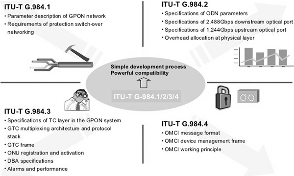
- G.984.3 − This document describes the Gigabit-Capable Passive Optical Network Transmission Convergence Layer Specification.
- G.984.4 − This document describes the Gigabit-Capable Passive Optical Network ONT Management and Control Interface Specification (OMCI).
GPON Architecture
GPON OLT serves multiple ONTs through the PON port. The downstream transmission, i.e., from OLT to ONT is usually TDM; whereas the upstream traffic, i.e., from ONT to OLT is usually TDMA.

PON system may be symmetrical or asymmetrical. PON and fiber infrastructure can also be used for supporting any one-way distributive service. For example Video at a different wavelength.
GPON Physical-Media Dependent Layer
G.984.2 is the specification of the physical layer of the GPON system. The physical layer addresses areas such as −
- Optical performance in terms of data rate.
- The class of optical fiber components.
- The timing and control of the optical power.
- Forward error correction.
One of the basic requirements of an optical system is to provide components with sufficient capacity to extend the optical signal to the expected range. There are three categories or classes of components, which are based on power and sensitivity. The classes of components are −
- Class A optics: 5 to 20dB
- Class B optics: 10 to 25dB
- Class C optics: 15 to 30dB
Optical Line Terminal (OLT)
The OLT provides the service node interface (SNI) (typically 1 Gbps and/or 10 Gbps Ethernet LAN interfaces) towards the core network, and controls the GPON. The OLT consists of three major parts −
- Service port interface function
- Cross-connect function
- Optical distribution network (ODN) interface
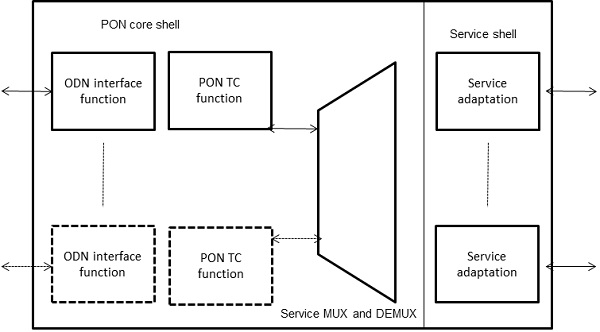
The following illustration shows the typical OLT functional block diagram.
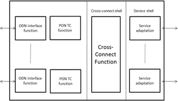
PON Core Shell
PON Core shell consists of two parts. The first part is ODN interface function and the part is PON TC function. PON TC function includes OAM, media access control, framing, DBA, delineation of protocol data unit (PDU) for the cross-connect function, and for the ONU management.
Cross-connect shell − This shell provides a communication path between the PON core shell and the service shell.
Service shell − This shell is for translation between service interfaces and the TC frame interface of the PON section.
ONU/ONT
The Optical Network Unit (ONU) operates with a single PON interface or maximum two interfaces for link protection purposes. In case, any one fiber out of these two fibers is cut the ONU can be accessed through other fiber. This is called PON protection or Link Protection. Link protection is also known as link aggregation, which can protect the link and the same time, it can aggregate the traffic as well.
The service MUX and DEMUX function connects the Customer devices to PON side. The Optical Network Terminal (ONT) is designed for single subscriber use, while the ONU (Optical Networking Unit) is designed for multiple subscriber use. The splitters allow the PON to be shared by up to 128 ONTs or ONUs.
ONT/ONU Interfaces
The optical network terminal (ONT), which is connected to the OLT at uplink side for service network interface, has many user-network interface ports. Typically, there will be four FE/GE ports towards UNI.
UNI Ports for Residential ONT − Typically, the subscriber service interfaces such as 10/100Base-T High Speed Internet (HSI) and video over IP, RF coaxial for RF video overlay systems, and FXS telephone interfaces analog for VoIP PSTN voice.
UNI ports for a business ONT − In addition to the above, may also include 10/100/100Base-T routers and L2 / L3 switches interfaces and DS1/E1 PBX for key systems.
The optical network unit (ONU) terminates the GPON fiber and has much more user network interface (UNI) to multiple subscribers. UNI interface can be ADSL2+, VDSL2, Power Line, MoCA or HPNA, and the distance to the subscriber (10/100 Base-T is limited to 100m, which is 330 ft.).
According to the type of interface ports, UN UNI may not be able to connect directly to a subscriber CPE equipment. In this case, the UN UNI connects to a network termination (NT), which is placed at the final location of the subscriber. NT terminates the CPE equipment of the subscriber, such as a PC, Wireless Router, Telephone, IP Video Set-Top Box, or Set-Top Box, RF Video, etc.
Essentially, an ONT combines the function of an ONU and an NT in a single device. This combination of the two; together makes the ONT the most cost effective solution to provide GPON services to local and single-family, small, and medium enterprises. However, if a client on campus as students, hostels, schools, colleges, hospitals, or corporate offices, where there is already CAT-5 copper cable is laid, ONU can serve as a more appropriate solution.
Optical Distribution Network
The GPON ODN, consisting of a single mode optical fiber and cable; the optical fiber ribbon cables, splices, optical connectors, passive optical splitters and passive branching components are very passive.
The ODN optical splitters divide the single fiber into multiple fibers going to different buildings and individual homes. The splitters can be placed in any location in the ODN, from the Central Office (CO)/ Local Exchange (LE) to the customer premises and may be of any size. The splitters are designated as [n:m], where n is the number of input (towards OLT) = 1 or 2, and m is the number of outputs (towards ONT) = 2,4,8,16,32,64.
GPON Multiplexing/ Framing
The GPON multiplexing or framing is explained with the following factors.
GPON Encapsulation Method (GEM)
It is the data transport scheme in the specified GPON transmission convergence layer. GEM provides a connection-oriented, variable-length framing mechanism for transport of data services over the passive optical network (PON). GEM is designed to be independent of the type of the service node interface at the OLT as well as the types of UNI interfaces at the ONUs.
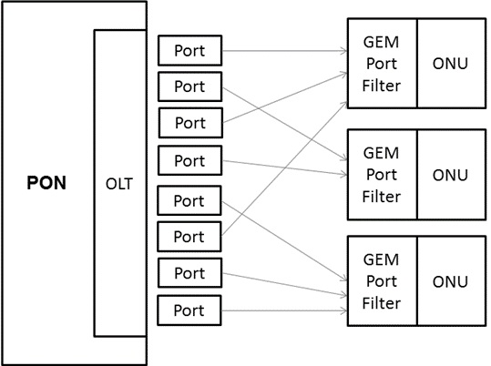
Downstream Traffic (OLT towards ONU/ONT)
For downstream traffic, the traffic multiplexing functions are centralized in OLT. A GEM Port-ID, in the form of a 12-bit number assigned by the OLT to the individual logical connections, identifies the GEM frames that belong to different downstream logical connections. Each ONU filters the downstream GEM frames based on their GEM Port-IDs and processes only the GEM frames that belong to the ONU.
Upstream Traffic (ONU/ONT towards OLT)
The traffic bearing entities within the ONU are granted upstream transmission opportunity (or bandwidth allocation) by the OLT. These traffic-bearing entities are identified by the allocation IDs (Alloc-IDs). The allocation identifier (Alloc-ID) is a 12-bit number that the OLT assigns to an ONU to identify a traffic-bearing entity. It is a recipient of upstream bandwidth allocations within the ONU.
The bandwidth allocations to different Alloc-IDs are multiplexed in time as specified by the OLT in the bandwidth maps transmitted downstream. Within each bandwidth allocation, the ONU uses the GEM Port-ID as a multiplexing key to identify the GEM frames that belong to different upstream logical connections.
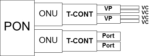
A Transmission container (T-CONT) is an ONU object representing a group of logical connections. It appears as a single entity for the purpose of upstream bandwidth assignment on the PON. Based on the mapping scheme, service traffic is carried to different GEM ports and then to different T-CONTs.
The mapping between the GEM port and the T-CONT is flexible. A GEM Port can correspond to a T-CONT; or multiple GEM Ports can correspond to the same T-CONT.
G-PON Transmission Convergence Layer (GTC)
A protocol layer of the G-PON protocol suite that is positioned between the physical media dependent (PMD) layer and the G-PON clients. The GTC layer is composed of GTC framing sub-layer and GTC adaptation sub-layer.
In the downstream direction, the GEM frames are carried in the GTC payload, which arrive at all the ONUs. The ONU framing sub-layer extracts the frames, and the GEM TC adapter filters the frames based on their 12-bit Port-ID. Only frames with the appropriate Port-IDs are allowed through to the GEM client function.
In the upstream direction, the GEM traffic is carried over one or more T-CONTs. The OLT receives the transmission associated with the T-CONT and the frames are forwarded to the GEM TC adapter and then the GEM client.
GTC Layer Framing
The downstream frame has a duration of 125 microseconds and is 38880 bytes long, which corresponds to the downstream data rate of 2.48832 Gbit/s. The downstream GTC frame consists of the physical control block downstream (PCBd) and the GTC payload section.
GPON Transmission Convergence frames are always 125 Msec long −
- 19440 bytes/frame for 1244.16 rate
- 38880 bytes/frame for 2488.32 rate
Each GTC frame consists of Physical Control Block downstream + payload
- PCBd contains sync, OAM, DBA info, etc.
Payload may have ATM and GEM partitions (either one or both)
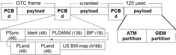
The upstream GTC frame duration is 125 s. In G-PON systems with the 1.24416 Gbit/s uplink, the upstream GTC frame size is 19,440 bytes. Each upstream frame contains a number of transmission bursts coming from one or more ONUs.
Each upstream transmission burst contains an upstream physical layer overhead (PLOu) section and one or more bandwidth allocation intervals associated with the individual Alloc-IDs. The downstream GTC frame provides the common time reference for the PON and the common control signaling for the upstream.
GPON Payloads
GTC payload potentially has two sections −
- ATM partition (Alen * 53 bytes in length)
- GEM partition (now preferred method)

ATM Partition
The ATM partition has the following characteristics.
- Alen (12 bits) is specified in the PCBd.
- Alen specifies the number of 53B cells in the ATM partition.
- If Alen = 0 then no ATM partition.
- If Alen = payload length/53, then no GEM partition.
- ATM cells are aligned to GTC frame.
- ONUs accept ATM cells based on VPI in ATM header.
GEM Partition
The GEM partition has the following characteristics.
- Unlike ATM cells, GEM delineated frames may have any length.
- Any number of GEM frames may be contained in the GEM partition.
- ONUs accept GEM frames based on 12b Port-ID in GEM header.
GPON Encapsulation Mode
A common complaint against BPON was inefficiency due to the ATM cell tax. GEM is similar to ATM. It has constant-size HEC-protected header. However, it avoids large overhead by allowing variable length frames. GEM is generic any packet type (and even TDM) supported. GEM supports fragmentation and reassembly.
GEM is based on GFP, and the header contains the following fields −
- Payload Length Indicator - payload length in Bytes.
- Port ID - identifies the target ONU.
- Payload Type Indicator (GEM OAM, congestion/fragmentation indication).
- Header Error Correction field (BCH(39,12,2) code+ 1b even parity)
The GEM header is XOR'ed with B6AB31E055 before transmission.

Ethernet/TDM over GEM
When transporting Ethernet traffic over GEM
- Only MAC frame is encapsulated (no preamble, SFD, EFD)
- MAC frame may be fragmented (see next slide).
Ethernet over GEM
When transporting TDM traffic over GEM −
- TDM input buffer polled every 125 Msec.
- PLI bytes of TDM are inserted into payload field.
- Length of TDM fragment may vary by ± 1 Byte due to frequency offset.
- Round-trip latency bounded by 3 msec.

TDM over GEM

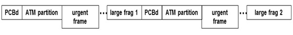
GEM can fragment its payload. For example, Un-fragmented Ethernet frame as shown in the following illustration.

The following illustration depicts a Fragmented Ethernet frame.

GEM fragments payloads for either of the following two reasons −
Reason 1 − GEM frame may not straddle GTC frame.

Reason 2 − GEM frame may be pre-empted for delay-sensitive data.
GPON Encryption
OLT encrypts using AES-128 in the counter mode. Only payload is encrypted (not ATM or GEM headers). Encryption blocks are aligned to the GTC frame. Counter is shared by OLT and all ONUs as follows −
- 46b = 16b intra-frame + 30 bits inter-frame.
- Intra-frame counter increments every 4 data bytes.
- Reset to zero at beginning of DS GTC frame.
OLT and each ONU must agree on a unique symmetric key. OLT asks ONU for a password (in PLOAMd). ONU sends password US in the clear (in PLOAMu) −
- Key sent 3 times for robustness
OLT informs ONU of precise time to start using new key.
QoS GPON
GPON treats QoS explicitly. Constant length frames facilitate QoS for time-sensitive applications. There are 5 types of Transmission Containers −
- Type 1 − fixed BW.
- Type 2 − assured BW.
- Type 3 − allocated BW + non-assured BW.
- Type 4 − best effort.
- Type 5 − superset of all of the above.
GEM adds several PON-layer QoS features −
- Fragmentation enables pre-emption of large low-priority frames.
- PLI - explicit packet length can be used by queuing algorithms.
- PTI bits carry congestion indications.
In the next chapter, we will understand what Ethernet Passive Optical Network is.
FTTH - EPON
The Ethernet Passive Optical Network (EPON) is a PON encapsulate data with Ethernet and can offer 1 Gbps to 10 Gbps capacity. EPON follows the original architecture of a PON. Here, the DTE connected to the trunk of the tree and called as Optical Line Terminal (OLT) as shown in the following illustration.
It is usually located at the service provider, and the connected the DTE branches of the tree are called Optical Network Unit (ONU), located in the premises of the subscriber. The signals from the OLT pass through a passive splitter to achieve the ONU and vice versa.
Ethernet in the First Mile
The standardization process began when a new study group called Ethernet in the First Mile (EFM) was established in November 2000, having as main objectives the study of Ethernet point-to-multipoint (P2MP) fiber with Ethernet copper. Ethernet over point-to-point (P2P) fiber and over a network operating mechanism, Administration and Maintenance (OAM) to facilitate network operation and troubleshooting. The EFM working group ends the process of normalization with the ratification of the IEEE Std 802.3ah in June 2004.
A product by EFM (Ethernet in the first mile). A PON technology based on Ethernet. It is based on a Major standard IEEE 802.3ah. Based upon Multi-Point Control Protocol (MPCP), defined as a function within the MAC control sub-layer, to control access to a P2MP topology.
The basis of EPON/MPCP protocol lies in the point-to-point (P2P) emulation sublayer. Its Transmission rate is → symmetric 1.25G; distance10KM/20KM; splitter ratio > 1:32. The EFM points out many advantages of EPON based on Ethernet as core technology, including protocols maturity, technology simple, extension flexibility, and users oriented.
EPON system does not choose expensive ATM hardware and SONET equipments, making it compatible to the existing Ethernet network. It simplifies system structure, decreases cost, and makes itself flexible to upgrade. Equipment venders focus on optimizing the function and practicability.
BPON ATM Systems
BPON ATM based systems have proven to be very inefficient, as a vast majority of traffic across the access network consists of large IP Frames and variable sizes. It has created the opportunity for the development of pure Ethernet based EPON, GigE password enjoying QoS, and cost-effective integration with other emerging Ethernet equipment. Ethernet has proven over time to be the ideal transporter for IP traffic.
Accordingly, the IEEE 802.3ah standard 802.3 instructed the "Ethernet in the First Mile" working group with the development of standards for point-to-point and point-to-multipoint access networks, the latter indicating Ethernet PON. EPON is currently a part of the Ethernet standard.
Development of Passive Optical Network (GPON) i.e. Gigabit-equipped standard (G.984 series) has really began after the proposals of the FSAN members (Quantum Bridge, Al) for an ATM/Ethernet PON solution. Gbps, which is independent of the protocol, was not very popular within the IEEE 802.3ah working group. FSAN has decided to pursue this as a different competing standard to the ITU.
EPON and GPON draw heavily from G.983, the standard of BPON, when it comes to general concepts that work well (operating PON Optical Distribution Network (ODN), wavelength plan and application). They both offer their own version of enhancements to accommodate better size IP/Ethernet frames at variable rates Gbps.
IEEE 802.3ah Ethernet standard specified access network and it also known as Ethernet in the First Mile as well. Section five of IEEE802.3ah makes up the IEEE Std 802.3 that corresponds to the definition of services and protocol elements. It allows the exchange of IEEE 802.3 format frames between stations in a subscriber access network.
Concept of EPON
EFM has introduced the concept of EPON in which a point-to-multipoint (P2MP) network topology is implemented with passive optical splitters. However, the Ethernet point-to-point fiber offers the highest bandwidth at a reasonable cost. Ethernet Point-to-multipoint fiber provides relatively high bandwidth at a lower cost. The purpose of the IEEE Std 802.3ah was to extend the application of Ethernet to include access subscriber networks to provide a significant increase in performance while minimizing equipment costs of operation and maintenance.
The conclusion of the IEEE 802.3ah EFM standard significantly expands the range and reach of Ethernet transport for the use in access and metro networks. This standard allows service providers a variety of flexible and cost effective solutions for the provision of broadband Ethernet services in the access and the metro networks.
EFM covers a family of technologies that differ in the type of media and signaling speed - it is designed to be deployed in the networks of a type or multiple (s) FSM media as well as interact with mixed 10/100/1000/10000 Mb/s Ethernet networks. Any network topology defined in IEEE 802.3 can be used on the premises of the subscriber and then connected to an Ethernet subscriber access network. EFM technology allows different types of topologies to achieve maximum flexibility.
IEEE Std 802.3ah
IEEE Std 802.3ah includes specifications for Ethernet access networks of the subscriber and IEEE Std 802.3ah EPON supports a nominal rate of some 1 Gb/s (expandable to 10 Gb/s) for each channel. These are defined by two wavelengths: a downstream wavelength and one for the shared upstream direction between the user devices.
EFM supports full duplex links, so that a full duplex simplified Media Access Control (MAC) can be defined. Ethernet architecture divides the physical layer in a Physical Medium Dependent (PMD), Physical Medium Attachment (PMA), and Physical Coding Sublayer (PCS).
EPON implements a P2MP network topology with appropriate extensions to the undercoat and reconciliation sublayer MAC control, and optical fiber under layers physical medium dependent (PMD) to support this topology.
Physical Layer
For P2MP topologies, EFM introduced a family of signaling systems for the physical layer that are derived from 1000BASE-X. However, it includes extensions of the RS, PCS, and PMA, with an optional forward error correction (FEC) capacity. 1000BASE-X PCS and PMA sublayers map the characteristics of the interface. The PMD sublayer (including MDI) the services expected by the undercoat reconciliation. 1000BASE-X can be extended to support other full duplex media - requires only that the environment is consistent with the level of PMD.
Medium Load Interface (MDI)
It is the interface between PMD and the physical media. It describes the signals, the physical media, and the mechanical and electrical interfaces.
Physical Medium Dependent (PMD)
PMD is responsible for the interface to the transmission medium. PMD generates electrical or optical signals depending on the nature of the physical medium connected. 1000BASE-X connections over PON to at least 10 kilometers and 20 kilometers (undercoats 1000BASE-PX10 and 1000BASE-PX20 PMD) provide P2MP.
In a PON Ethernet, D and U suffixes indicate PMD at each end of the link, which transmits in these directions and receives in the opposite direction, i.e., a single downstream PMD is identified as 1000BASE-PX10-D and upstream 1000BASE-PX10 U PMD. The same fibers are used simultaneously in both the directions.
A 1000BASE-PX-U PMD or 1000BASE-PX-D PMD is connected to the appropriate PMA 1000BASE-X and to support via the MDI. PMD is optionally combined with management features that can be accessed via the management interface. To allow the upgrade possibilities in the case of 10 km or 20 km Pons, both 1000BASE-PX20-D 1000BASE-PX10 PMD and PMDU are inter-operable with each other.
Physical Medium Attachment (PMA)
PMA includes the transmission, receipt, clock recovery, and align functions. The PMA provides an independent middle way for PCS to support the use of a range of bit-oriented physical media series. The sublayer of physical coding (PCS) comprises codifications bit functions. The PCS interface is Gigabit media independent interface (GMII), which provides a uniform interface to the Reconciliation sublayer for all implementations of 1000 Mb/s PHY.
Gigabit Media Independent Interface (GMII)
The interface GMII refers to the interface between the Gigabit MAC layer and the physical layer. It allows multiple DTE mixed with a variety of implementations from the speed gigabit physical layer. The PCS Service Interface allows 1000BASE-X PCS to transfer information to and from a PCS customer. PCS customers include MAC (via the undercoat of reconciliation) and repeater. The PCS interface is defined precisely as the Gigabit Media Independent Interface (GMII).
The Reconciliation sublayer (RS) ensures the matching of GMII signals defining the serviceaccess control medium. GMII and RS are used to provide independent media so that an access controller identical media can be used with any type of copper and optical PHY.
Data Link Layer (Multipoint MAC Control)
MAC control protocol was specified to support and new functions to be implemented and added to the standard at the same time. It is the case of multi-point control protocol (MPCP). The management protocol to P2MP is one of the functions defined by the Multi-Point Control Protocol.
The multipoint MAC control functionality is implemented to access devices of the subscriber containing physical layer devices point to multipoint. Commonly, MAC emulation jurisdictions provide a point-to-point service between OLT and the ONU, but an additional instance is now included with a communication goal for all ONUs at a time.
MPCP (Multi-Point Control Protocol)
MPCP is very flexible, easy to implement. MPCP uses five types of messages (each message is a MAC Control frame) and ONU/ONT reports multiple packet boundaries, OLT grants on a packet boundary no delineation overhead.
The MPCP indicates system between an OLT and ONUs associated with a Point-to-Multi-Point (P2MP) PON portion to permit productive transmission of information in the UPSTREAM heading.
MPCP performs the following functions −
- MPCP controls Auto Discovery process.
- Timeslot/Bandwidth assignment to ONTs.
- Timing Reference provided to synchronize ONTs.
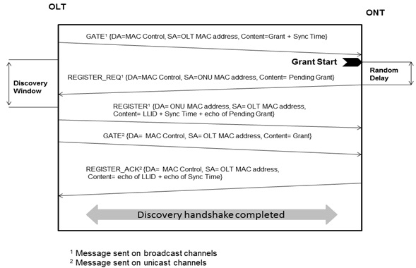
MPCP has introduced five new MAC control messages −
- Gate, Report
- Registered REQ
- Register
- Registered ACK
- Auto Discovery
Message Discovery Sequence Summary
The following illustration depicts the Message Discovery Sequence Summary.
DBA EPON
In EPON, the communication between OLT and ONY is regarded as downstream, OLT broadcast downstream data towards ONT using the entire bandwidth and on other end ONT receives the fames using information available on Ethernet Frames. The upstream from ONT to OLT is using single channel communication, means one channel will be used by multiple ONTs, which means data collision.
To avoid this problem, effective bandwidth allocation scheme is required, which can assign resources equally to ONTs as the same time ensuring the QoS, this scheme is known as Dynamic Bandwidth Allocation (DBA) algorithm. The DBA uses report and gate messages to build transmission schedule to be conveyed to the ONTs.
DBA Characteristics
An important feature of EPON is to provide different services with optimum QoS and effective allocation of bandwidth using different DBA allocation to meet the demand of current and future applications.
Presently, following are the two different types of DBA algorithms available for the EPON −
- The first one is for accommodating traffic fluctuations.
- The second one is to provide QoS to different types of traffic.
The other characteristics are to avoid Frame Collisions, Managements of Real Time Traffic through QoS and Management of Bandwidth for each Subscriber along with Decrease Delay on Low Priority Traffic.
EPON Frame Format
EPON operation is based on the Ethernet MAC and EPON frames are based on GbE frames, but extensions are needed −
Clause 64 − Multi-Point Control Protocol PDUs. This is the control protocol implementing the required logic.
Clause 65 − Point-to-point emulation (reconciliation). This makes the EPON looks like a point-to-point link and EPON MACs have some special constraints.
Instead of CSMA/CD, they transmit when granted.
Time through MAC stack must be constant (± 16-bit durations).
Accurate local time must be maintained.
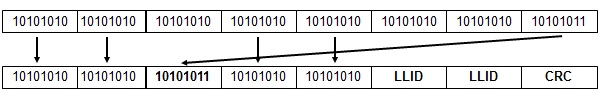
EPON Header
Standard Ethernet starts with an essentially content-free 8B preamble −
- 7B of alternating ones and zeros 10101010
- 1B of SFD 10101011
In order to hide the new PON header, EPON overwrites some of the preamble bytes.
LLID field contains the following factors −
MODE (1b) −
- Always 0 for ONU
- 0 for OLT unicast, 1 for OLT multicast/broadcast
Actual Logical Link ID (15b) −
- Identifies registered ONUs
- 7FFF for broadcast
CRC protects from SLD (byte 3) through LLID (byte 7).
Security
Downstream traffic broadcasts to all ONUs, so it becomes easy for a malicious user to reprogram ONU and capture desired frames.
Upstream traffic has not been exposed to other ONUs, so encryption is not needed. Do not consider fiber-tappers because EPON does not provide any standard encryption method, but −
- Can supplement with IPsec or MACsec and
- Many vendors have added proprietary AES-based mechanisms.
BPON used a mechanism called churning Churning was a low cost hardware solution (24b key) with several security flaws, such as −
- Engine was linear - simple known-text attack.
- 24b key turned out to be derivable in 512 tries.
Therefore, G.983.3 added AES support, which is now used in GPON.
QoS EPON
Many PON applications require high QoS (e.g. IPTV) and EPON leaves QoS to higher layers like −
- VLAN tags.
- P bits or DiffServ DSCP.
In addition to these, there is a crucial difference between LLID and Port-ID −
- There is always 1 LLID per ONU.
- There is 1 Port-ID per input port - there may be many per ONU.
- This makes port-based QoS simple to implement at PON layer.
EPON vs GPON
The following table illustrates the comparative features of EPON and GPON −
| GPON(ITU-T G.984) | EPON(IEEE 802.3ah) | |
|---|---|---|
| Downlink/Uplink | 2.5G/1.25G | 1.25G/1.25G |
| Optical Link Budget | Class B+:28dB;Class C: 30dB | PX20: 24dB |
| Split ratio | 1:64 --> 1:128 | 1:32 |
| Actual downlink bandwidth | 2200~2300Mbps 92% | 980Mbps 72% |
| Actual Uplink bandwidth | 1110Mbps | 950Mbps |
| OAM | Complete OMCI function + PLOAM + embed OAM | Flexible and simple OAM function |
| TDM service & synchronized clock function | Native TDM, CESoP | CESoP |
| Upgradeability | 10G | 2.5G/10G |
| QoS | DBA schedule contains T-CONT,PORTID; fix bandwidth/guarantee bandwidth/non-guarantee bandwidth/ best-effort bandwidth | Support DBA, QoS is supported by LLID and VLAN |
| Cost | 10%~20% higher cost than EPON currently, and almost same price in large volume | -- |
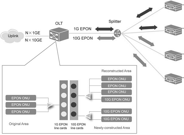
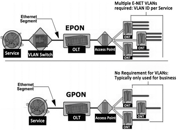
The following image shows the different structures of EPON and GPON −
FTTH - XPON Evaluation
The following illustration depicts XPON Evaluation.
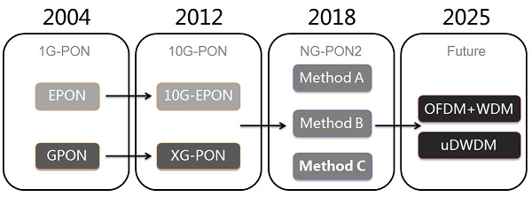
The following table explains different methods of XPON Evaluation.
| Multiplex Mode | Typical Technology | ||
|---|---|---|---|
| Method A | TDM | 40G TDM PON | OFDM PON |
| Method B | WDM | PtP WDM | |
| Method C | TDM + WDM | 40G TWDM PON | NG-EPON |
After GPON development, FSAAN and ITU-T started working on NG-PON with the following features −
- Low cost product
- Large Capacity
- Wide Coverage
- Backward compatibility
NG-PONs are divided into two phases by FSAN based on the current application demand and technology −
NG PON1 − NGPON1 is backward compatible with legacy GPON ODNs. NG-PON1 has an asymmetric 10G system with 10G downstream/download and 2.5G upstream/upload speed. This NG-PON1 is enhanced TDM PON system from GPON.
NG PON2 − NGPON2 is long-term PON evaluation, which can support as well as can be deployed over the new ODNs.
There are many ways to develop NG-PON2 unlike NG-PON1 to improve the bandwidth rate from 10G to 40G −
Using TDM technology same as being used for NG-PON1.
WDM PON (Using coarse wavelength division multiplexing (CWDM) or dense wavelength division multiplexing (DWDM).
ODSM PON (TDMA +WDMA).
OCDMA PON (Using CDMA technology).
O-OFDMA PON (Using FDMA technology).
Coexistence NG-PON1
The main feature of NG-PON1 is to provide higher bandwidth than GPON as the same time. It should be backward compatible with the existing GPON network, which will reduce the operators cost. This NG-PON defined by the FSAN and ITU-T is known as XG-PON1.
FSAN and ITU-T has defined the following data rates for XG-PON1 −
- Downstream Data Rate − 10G
- Upstream Data Rate − 2.5G
Upstream data rate of 2.5G is twice the upstream data rate of GPON. Apart from all elements of GPON, ODN (optical distribution network) can be reused in XG-PON1 network.
By adding only 10G downstream card in the existing GPON OLT, the GPON enhanced to XG-PON1.
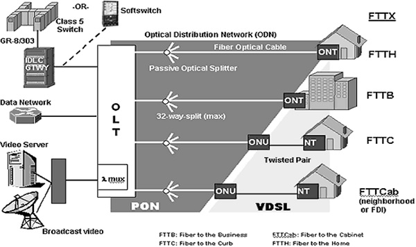
Network Architecture and Coexistence
As described above that XG-PON1 is an enhancement to existing GPON that can support different GPON deployments such as −
- Point-to-multipoint (P2MP) architecture of GPON
- Fiber to the home (FTTH)
- Fiber to the cell (FTTCell)
- Fiber to the building (FTTB)
- Fiber to the curb (FTTCurb)
- Fiber to the cabinet (FTTCabinet)
The following illustration shows the different GPON deployments, which can be further enhanced with XG-PON1 −
Generally, there are two types of deployments −
- Green Field Deployment
- Brown Field Deployment
Green field is used where a complete new deployment is required, whereas in the Brownfield deployment, existing infrastructure will be used. So, for the Brown Field (only of GPON network) deployments, XG-PON1 can be used. In case, when copper network needs to be replaced with the fiber network, then it will be considered under the Green Field Network, as the existing network will be replaced with the new network completely.
Physical Layer
Physical layer specifications for XG-PON1 were frizzed on Oct. 2009 and published on March 2010 by ITU-T. Downstream wavelength of 1575-1580 nm is selected by FSAN. C band. L band, and O band were compared in the selection of upstream wavelength, but C band was eliminated due to overlapping with RF video channels. Since, sufficient band guard was not available on L band and due to this, the same was also eliminated and all comparison with respect to pros and cons O- band was chosen because O+ has higher requirement on filters.
| Item | Specifications |
|---|---|
| Optical Fiber | ITU-T G.652 |
| Upstream Wavelength Plan | 1260 to 1280 nm |
| Downstream Wavelength Plan | 1575 to 1580 nm |
| Power Budget | XG-PON1: 14 to 29dB XG-PON2: 16 to 31 dB |
| Data Rate | Upstream: 2.48832 Gbps Downstream: 9.95328 Gbps |
| Maximum physical reach | 20 Km |
| Maximum logical reach | 60 Km |
As per the above table, the downstream rate of XG-PON1 is 10 Gbps with the data rate of 9.5328 Gbps to keep the consistency with typical ITU-T rates, which is different from IEEE 10GE-PON, which is 10.3125 Gbps.
HTC Layer
The transmission layer (TC Layer) is known as XGTC (XG-PON1) transmission convergence layer, which optimizes the basic processing mechanism. The transmission convergence layer enhances the framing structure, activation mechanism, and DBA.
The enhancement in XG-PON1 framing structure is by aligning the frame and field design with word boundaries by matching the rate of XG-PON1. The DBA mechanism is more flexible with the upgradation, whereas the activation mechanism follows the same principle of GPON.
The two important features of XGTC layers are −
- Power Saving
- Security
Data encryption was an optional feature in GPON, whereas in xG-PON1 there are three methods for authentication −
First one is based on registration ID (Logical ID)
Second one is based on OMCI channels (inherited from GPON)
The third one is based on IEEE 802.1x protocols, which is a new bidirectional authentication scheme.
Upstream encryption and downstream-multicast encryption are also provided over XGTC layer.
Management and Configuration
For management and configuration ITU-T (G.984.4) recommendation was adopted in XG-PON1, which is also backward compatible with the GPON. As GPON uses the OMCI technology for management and configuration, similarly XG-PON1 uses more or less 90% of it with minor changes in ITU-T (G.984.4).
In both the cases (for GPON and XG-PON1) where lower layer technology is adopted is not a big concern as far as service is concerned. The important factor is to configure Layer 2 channel for proper forwarding of service data. All L2 configuration from the network side to user side is covered under OMCI L2 model.
The OMCI L2 model is used for both the technologies, i.e., GPON and XG-PON1 as the definition for network side and user side is same for both the technologies.
Interoperability
The most impressive part of GPON and XG-PON1 is interoperability. XG-PON1 is backward compatible with GPON, in other words, an ONT/ONU connected with GPON OLT can work with XG-PON1 OLT as well. A group was established in 2008 by FSAN, which is known as OISG (OMSI Implementation Study Group).
This group was restricted to study the (G.984.4) recommendations for OMCI interoperability for ONT management and control channel (OMCC), QoS management, multicast configuration, S/W version updates, and L2 configuration. The official number of [G.984.4] is [ITU-T G.impl984.4] and is called as the OMCI implementation guide as well.
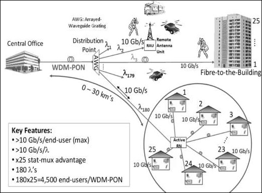
WDM-PON
The following illustration is for WDM-PON, which also shows an array of wave-guide gratings (AWGs). These are used for the MUX and DEMUX wavelength.
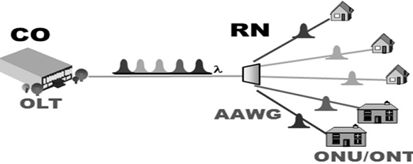
P2MP WDM-PON
In WDM-PON, different wavelength is required for different ONT. Each ONT gets an exclusive wavelength and enjoys the bandwidth resources of the wavelength. In other words, WDM-PON works on a logical Point-to-Multi Point (P2MP) topology.
In the WDM-PON, AWG is needed to be between OLT and ONT. Each port of the AWG is wavelength dependent and the optical transceiver on each ONT transmits optical signals in a specified wavelength determined by the port on the AWG.
In WDM technology, the transceivers with specified wavelengths are called colored optical transceivers and the transceiver, which is can be used for any wavelength is known as colorless transceiver. There is a complexity of using colored optical transceivers, which processing service is provisioning and devising storage.
AWG components are temperature sensitive due to this, there are certain challenges for WDMPON as to address the real-time consistency between the wavelength of optical transceivers and the connecting AWG port and between the wavelengths of the port on the local AWG (at the CO) and the port on the remote AWG.
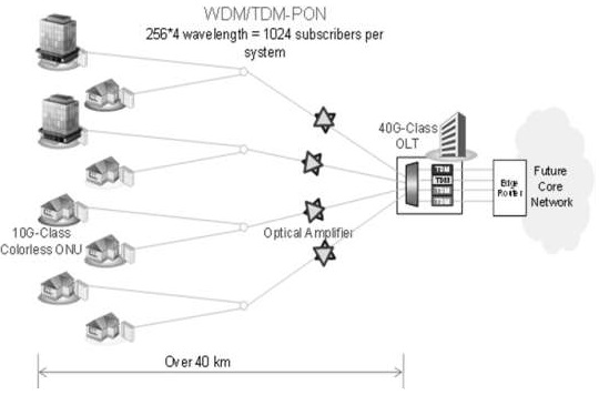
ODSM-PON
In ODSM-PON, the network remains unchanged from CO to user premises except one change, which is active WDM splitter. A WDM splitter will be placed between OLT and ONT replacing passive splitter. In ODSM-PON, the downstream adopts WDM, means data towards ONT use different wavelength for different ONT and in upstream, ODSN-PON adopts dynamic TDMA + WDMA technologies.
XGPON Standards
The following table describes the XGPON standards.
| Release Time | Version | |
|---|---|---|
| G.987 | 2010.01 | 1.0 |
| 2010.10 | 2.0 | |
| 2012.06 | 3.0 | |
| G.987.1 | 2010.01 | 1.0 |
| G.987.1Amd1 | 2012.04 | 1.0amd1 |
| G.987.2 | 2010.01 | 1.0 |
| 2010.10 | 2.0 | |
| G.987.2Amd1 | 2012.02 | 2.0amd1 |
| G.987.3 | 2010.10 | 1.0 |
| G.987.3Amd1 | 2012.06 | 1.0amd1 |
| G.988 | 2010.10 | 1.0 |
| G.988Amd1 | 2011.04 | 1.0amd1 |
| G.988Amd2 | 2012.04 | 1.0amd2 |
GPON − ITU and FSAN standardized in 2005, compliance with the G.984 × series standards.
NGPON1 −
G.987/G.988 XGPON standards have been released in 2011.
It standardized the XGPON with 2.5 Gbps upstream/10Gbps downstream.
GPON and XGPON use different wavelength for coexisting in one network.
NGPON2 −
Do not consider being compatible with existing ODN network, a more open standard of PON technology.
Now focus to WDM PON and 40G PON.
Main Features of XG-PON1
The following table describes the main features of XG-PON1.
| Item | Requirement | Remark |
|---|---|---|
| Downstream (DS) speed | Nominal 10 Gbit/s | |
| Upstream (US) speed | Nominal 2.5 Gbit/s | XG-PON with 10 Gbit/s US speed is denoted as XGPON2. It is for future study. |
| Multiplexing Method | TDM (DS)/ TDMA (US) | |
| Loss Budget | 29 dB and 31 dB (Nominal Classes) | Extended class is for future study. |
| Split Ratio | At least 1:64 (1:256 or more in the logical layer) | |
| Fiber Distance | 20Km (60 Km or more logical distance) | |
| Coexistence | With GPON (1310/1490 nm) With RF-Video (1550 nm) |
XG-PON Optical Power Class
The following table describes the minimum and maximum loss of XG-PON optical power class.
| 'Nominal1' class (N1 class) | 'Nominal2' class (N2 class) | 'Extended1' class (E1 class) | 'Extended2' class (E2 class) | |
|---|---|---|---|---|
| Minimum loss | 14 dB | 16 dB | 18 dB | 20 dB |
| Maximum loss | 29 dB | 31dB | 33 dB | 35 dB |
FTTH - Optical Distribution Network
In this chapter, let us understand what Split Ratios, Maximum Reach and Traffic Management are in the Optical Distribution Network (ODN).
The maximum permissible optical power attenuation between OLT optical ports to ONT input is 28dB, which is by utilizing the so-called Class B optical network elements. ODN Class A, B, and C are differentiated mainly on the optical transmitter power output and bit-rate optical receiver sensitivity. Class A gives the least optical-budget and Class C gives the highest, while cost wise they are in the same order. For maximum 1:64 split ratio, Class B optics is commonly deployed on commercial basis.
The comparison of class A, B, and C ODN optics is shown in the table given below −
Comparison of ODN Class A, B, and C Optics
| S.No. | Parameter | Unit | Class A | Class B | Class C | Remarks |
|---|---|---|---|---|---|---|
| 1 | Attenuation range (ITU-T Rec. G.982) | dB | 5 20 | 10 - 25 | 15 - 30 | |
| 2 | 2488 Mbps downstream direction | |||||
| 2.1 | OLT Transmitter | |||||
| 2.1.1 | Mean launched power MIN | dBm | 0 | +5 | +3 | Single fiber |
| 2.1.2 | Mean launched power MAX | dBm | +4 | +9 | +7 | Single fiber |
| 2.1.3 | Mean launched power MIN | dBm | 0 | +5 | +3 | Dual fiber |
| 2.1.4 | 2.1.4 Mean launched power MAX | dBm | +4 | +9 | +7 | Dual fiber |
| 2.2 | ONU Receiver | |||||
| 2.2.1 | Minimum sensitivity | dBm | -21 | -21 | -28 | Single fiber |
| 2.2.2 | Minimum overload | dBm | -1 | -1 | -8 | Single fiber |
| 2.2.3 | Minimum sensitivity | dBm | -21 | -21 | -28 | Dual fiber |
| 2.2.4 | Minimum overload | dBm | -1 | -1 | -8 | Dual fiber |
| 3 | 1244 Mbps upstream direction | |||||
| 3.1 | ONU Transmitter | |||||
| 3.1.1 | Mean launched power MIN | dBm | -3 | -2 | +2 | Single fiber |
| 3.1.2 | Mean launched power MAX | dBm | +2 | +3 | +7 | Single fiber |
| 3.1.3 | Mean launched power MIN | dBm | -3 | -2 | +2 | Dual fiber |
| 3.1.4 | Mean launched power MAX | dBm | +2 | +3 | +7 | Dual fiber |
| 3.2 | OLT Receiver | |||||
| 3.2.1 | Minimum sensitivity | dBm | -24 | -28 | -29 | Single fiber |
| 3.2.2 | Minimum overload | dBm | -3 | -7 | -8 | Single fiber |
| 3.2.3 | Minimum sensitivity | dBm | -24 | -28 | -29 | Dual fiber |
| 3.2.4 | Minimum overload | dBm | -3 | -7 | -8 | Dual fiber |
Optical Signal Splitting
A single fiber starting from the OLT is split through passive optical splitters to serve 64 customer-premise ONTs. The same fiber carries both down-stream (OLT towards ONT) and up-stream (ONT towards OLT) bit streams viz., 2.488 Mbps/1490 nm (1480 - 1500nm window) and 1.244 Mbps/1310 nm (1260-1360nm window).
RF Overlay for TV Services
The TV signals (derived from a satellite Head End) are optionally broadcast on a third optical wavelength of 1550nm on same (or additional) fiber introduced into the FTTx system through an RF Overlay sub-system. CATV Signal can be coupled with GPON signal after amplification by EDFA. The RF CATV signals modulated onto the 1550 nm wavelength. It is extracted through a De-mux function, built inside the ONT, and routed to back plane service connection for the STB/TV.
