 Data Structure
 Networking
 RDBMS
RDBMS Operating System
 Java
Java MS Excel
 iOS
iOS HTML
HTML CSS
CSS Android
 Python
 C Programming
 C++
C++ C#
C# MongoDB
 MySQL
MySQL Javascript
 PHP
PHP
- Selected Reading
- UPSC IAS Exams Notes
- Developer's Best Practices
- Questions and Answers
- Effective Resume Writing
- HR Interview Questions
- Computer Glossary
- Who is Who
Explain the ATM Cell Structure in Computer Network
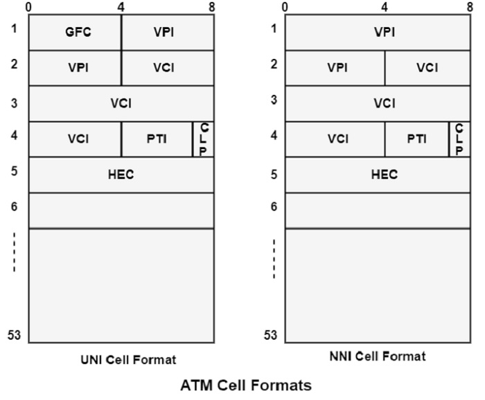
ATM transfers data in fixed-size units are known as cells. Each cell includes 53 octets or bytes, as shown in the figure. The first 5 bytes contain cell-header data, and the remaining 48 include the payload (user information).
Small, fixed-length cells are well appropriated to transfer voice and video traffic due to such traffic is biased to delays that result from having to wait for a huge data packet to download, among other things.
| Header | Payload |
|---|---|
| 5 Bytes | 48 Bytes |
ATM Cell Format
An ATM cell header can be two formats, such as User Network Interface (UNI) or Network to Network Interface (NNI). The UNI header can be used for communication between ATM endpoints and ATM switches in private ATM networks. The NNI header can be used for communication between ATM switches.
The figure shows the ATM UNI cell header format and the ATM NNI cell header format. Unlike the UNI, the NNI header does not contain the Generic Flow Control (GFC) field. The NNI header has a Virtual Path Identifier (VPI) field that appears in the first 12 bits. It is allowing for high trunks between public ATM switches.

ATM Cell Header Fields
The following definitions summarise the ATM cell header fields as shown in the figure above −
Generic Flow Control (GFC) − It supports local functions, such as recognizing multiple stations that send a single ATM interface. This field is generally not used and is set to its default value of 0 (binary 0000).
Virtual Path Identifier (VPI) − In conjunction with the Virtual Channel Identifier (VCI), it recognises the next destination of a cell as it transfers through a series of ATM switches on the way to its destination.
Virtual Channel Identifier (VCI) − In conjunction with the VPI, it recognizes the next destination of a cell as it transfers through a series of ATM switches on the way to its destination.
Payload Type (PT) − It denotes in the first bit whether the cell includes user data or control data. If the cell includes user data, the bit is set to 0. If it includes control data, it is set to 1. The second bit denotes congestion (0 = no congestion, 1 = congestion), and the third bit denotes whether the cell is the last in a sequence of cells that define a single AAL5 frame (1 = last cell for the frame).
Cell Loss Priority (CLP) − It denotes whether the cell should be removed if it encounters extreme congestion as it transfers through the network. Suppose the CLP bit similar is to 1, and the cell should be discarded in preference to cells with the CLP bit equal to 0.
Header Error Control (HEC) − It evaluates checksum only on the first 4 bytes of the header. It can be valid a single bit error in these bytes, thereby preserving the cell instead of discarding it.

