
Article Categories
- All Categories
-
 Data Structure
-
 Networking
-
 RDBMS
RDBMS
-
 Operating System
-
 Java
Java
-
 MS Excel
-
 iOS
iOS
-
 HTML
HTML
-
 CSS
CSS
-
 Android
-
 Python
-
 C Programming
-
 C++
C++
-
 C#
C#
-
 MongoDB
-
 MySQL
MySQL
-
 Javascript
-
 PHP
PHP
-
 Economics & Finance
8085 Executing the program and checking result
In this section we will see how to use 8085 to write a program in 8085 kit. We will also see how to debug the program and check the result after successful execution.
Let us see a typical keypad structure of 8085 kit. (This keyboard pattern may vary indifferent kits of different manufacturers)
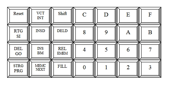
The following table will show the functionalities of different control keys. There are 16alphanumeric keys (0-9, A-F) to provide data and address −
| Keys | Functionalities |
|---|---|
| RESET | Reset the system |
| VCT INT | Vector Interrupt. It generates hardware interruptRST 7.5 via keypad |
| SHIFT | Provides second level commands to all keys |
| GO | Execute the program |
| SI | Execute in Single Step Mode |
| EXREG | Examine Register. It allows to see the values of different registers. |
| PRE | Point to previous memory address |
| DEL | Delete a part of program |
| INS | Insert a part of program |
| B.M | Block Move. This helps to move a block of memory to any RAM area |
| FILL | Fill some RAM area with constant values |
| REL | Reallocates the program written for some memory area. |
| INS DATA | Insert one or more data into memory |
| STRING | Find a string of data lying at particular address/s |
| MEMC | Compare two blocks of memory for equality |
Now we will see a sample program, where sixteen bytes of data are stored in memory location sat 8050H to 805FH. Transfer the entire block of data to new memory locations starting at 8070H.
Program
| T-States | Address | HEX Codes | Labels | Mnemonics | Comments |
|---|---|---|---|---|---|
| 10 | 8000 | 21, 50, 80 | START | LXI H, 8050H | Set up HL as a pointer for source memory |
| 10 | 8003 | 11, 70, 80 | LXI D, 8070H | Set DE for destination address | |
| 7 | 8006 | 06, 10 | MVI B,10H | Set up B to count 16 bytes | |
| 4 | 8008 | 7E | NEXT | MOV A,M | Get data byte from source memory |
| 7 | 8009 | 12 | STAX D | Store data byte at destination | |
| 6 | 800A | 23 | INX H | Pointing HL to next source location | |
| 6 | 800B | 13 | INX D | Pointing DE to next destination | |
| 4 | 800C | 05 | DCR B | Decrement count | |
| 10 | 800D | C2, 08, 80 | JNZ NEXT | If counter is not 0, go to transfer next byte | |
| 5 | 8010 | 76 | HLT | Stop | |
| Total 17 bytes |
TotalT-States = Toutside_loop+Tinside_loop
= (10 + 10 + 7 + 5) + ((4 + 7 + 6 + 6 + 4 + 10) x 16 - 3)
= 32 + (37 x 16 – 3)
= 32 + 589
= 621
The debugging options of 8085 kit.
| Command | Function/Format |
|---|---|
| Examine/Modify Memory | Displays/Modifies the contents of a memory location EXAM MEM NEXT [[] NEXT/PREV] EXEC |
| Examine/Modify register | Displays/modifies 8085 register contents. EXAM REG |
| Single step | Executes a single user program instruction SINGLE STEP |
| Go | Transfers control from monitor to user program GO EXEC |
| Block move/Block copy | Moves/copies a block of data from one portion to another BLK MOVE |
| Insert | Inserts one or more instructions in the user program INSERT [ |
| Delete | Deletes one or more instructions inthe user program DELETE [ |
Demonstration of block move operation
InitialCondition of memory addresses
| Source Address | Value | Destination Address | Value |
|---|---|---|---|
| 8000 | 00H | 8100 | XXH |
| 8001 | 11H | 8101 | XXH |
| 8002 | 22H | 8102 | XXH |
| 8003 | 33H | 8103 | XXH |
| 8004 | 44H | 8104 | XXH |
| 8005 | 55H | 8105 | XXH |
| 8006 | 66H | 8106 | XXH |
| 8007 | 77H | 8107 | XXH |
| 8008 | 88H | 8108 | XXH |
| 8009 | 99H | 8109 | XXH |
Keys −
Final Condition of memory addresses
| Source Address | Value | Destination Address | Value |
|---|---|---|---|
| 8000 | 00H | 8100 | 00H |
| 8001 | 11H | 8101 | 11H |
| 8002 | 22H | 8102 | 22H |
| 8003 | 33H | 8103 | 33H |
| 8004 | 44H | 8104 | 44H |
| 8005 | 55H | 8105 | 55H |
| 8006 | 66H | 8106 | 66H |
| 8007 | 77H | 8107 | 77H |
| 8008 | 88H | 8108 | 88H |
| 8009 | 99H | 8109 | 99H |
Demonstration of block insert and block delete operations
InitialCondition of memory addresses
| Source Address | Value |
|---|---|
| 8000 | 00H |
| 8001 | 11H |
| 8002 | 22H |
| 8003 | 33H |
| 8004 | 44H |
| 8005 | 55H |
| 8006 | 66H |
| 8007 | 77H |
| 8008 | 88H |
| 8009 | 99H |
Keys −
FinalCondition of memory addresses
| Source Address | Value |
|---|---|
| 8000 | 00H |
| 8001 | 11H |
| 8002 | 22H |
| 8003 | 33H |
| 8004 | 44H |
| 8005 | AAH |
| 8006 | BBH |
| 8007 | CCH |
| 8008 | DDH |
| 8009 | EEH |
| 800A | 55H |
| 800B | 66H |
| 800C | 77H |
| 800D | 88H |
| 800E | 99H |
Here we are using the 32Kmemory space 62256 at U3 with address map of 8000H to FFFFH. Instead of using HLT (76H) instruction to end the program we can use RST 5(EFH) to return back to the monitor program. Because it helps us to debug whether a program has caused halt and hang or not.

8K+ Views
