- Digital Electronics - Home
- Digital Electronics Basics
- Types of Digital Systems
- Types of Signals
- Logic Levels And Pulse Waveforms
- Digital System Components
- Digital Logic Operations
- Digital Systems Advantages
- Number Systems
- Number Systems
- Binary Numbers Representation
- Binary Arithmetic
- Signed Binary Arithmetic
- Octal Arithmetic
- Hexadecimal Arithmetic
- Complement Arithmetic
- Base Conversions
- Base Conversions
- Binary to Decimal Conversion
- Decimal to Binary Conversion
- Binary to Octal Conversion
- Octal to Binary Conversion
- Octal to Decimal Conversion
- Decimal to Octal Conversion
- Hexadecimal to Binary Conversion
- Binary to Hexadecimal Conversion
- Hexadecimal to Decimal Conversion
- Decimal to Hexadecimal Conversion
- Octal to Hexadecimal Conversion
- Hexadecimal to Octal Conversion
- Binary Codes
- Binary Codes
- 8421 BCD Code
- Excess-3 Code
- Gray Code
- ASCII Codes
- EBCDIC Code
- Code Conversion
- Error Detection & Correction Codes
- Logic Gates
- Logic Gates
- AND Gate
- OR Gate
- NOT Gate
- Universal Gates
- XOR Gate
- XNOR Gate
- CMOS Logic Gate
- OR Gate Using Diode Resistor Logic
- AND Gate vs OR Gate
- Two Level Logic Realization
- Threshold Logic
- Boolean Algebra
- Boolean Algebra
- Laws of Boolean Algebra
- Boolean Functions
- DeMorgan's Theorem
- SOP and POS Form
- POS to Standard POS Form
- Minimization Techniques
- K-Map Minimization
- Three Variable K-Map
- Four Variable K-Map
- Five Variable K-Map
- Six Variable K-Map
- Don't Care Condition
- Quine-McCluskey Method
- Min Terms and Max Terms
- Canonical and Standard Form
- Max Term Representation
- Simplification using Boolean Algebra
- Combinational Logic Circuits
- Digital Combinational Circuits
- Digital Arithmetic Circuits
- Multiplexers
- Multiplexer Design Procedure
- Mux Universal Gate
- 2-Variable Function Using 4:1 Mux
- 3-Variable Function Using 8:1 Mux
- Demultiplexers
- Mux vs Demux
- Parity Bit Generator and Checker
- Comparators
- Encoders
- Keyboard Encoders
- Priority Encoders
- Decoders
- Arithmetic Logic Unit
- 7-Segment LED Display
- Code Converters
- Code Converters
- Binary to Decimal Converter
- Decimal to BCD Converter
- BCD to Decimal Converter
- Binary to Gray Code Converter
- Gray Code to Binary Converter
- BCD to Excess-3 Converter
- Excess-3 to BCD Converter
- Adders
- Half Adders
- Full Adders
- Serial Adders
- Parallel Adders
- Full Adder using Half Adder
- Half Adder vs Full Adder
- Full Adder with NAND Gates
- Half Adder with NAND Gates
- Binary Adder-Subtractor
- Subtractors
- Half Subtractors
- Full Subtractors
- Parallel Subtractors
- Full Subtractor using 2 Half Subtractors
- Half Subtractor using NAND Gates
- Sequential Logic Circuits
- Digital Sequential Circuits
- Clock Signal and Triggering
- Latches
- Shift Registers
- Shift Register Applications
- Binary Registers
- Bidirectional Shift Register
- Counters
- Binary Counters
- Non-binary Counter
- Design of Synchronous Counter
- Synchronous vs Asynchronous Counter
- Finite State Machines
- Algorithmic State Machines
- Flip Flops
- Flip-Flops
- Conversion of Flip-Flops
- D Flip-Flops
- JK Flip-Flops
- T Flip-Flops
- SR Flip-Flops
- Clocked SR Flip-Flop
- Unclocked SR Flip-Flop
- Clocked JK Flip-Flop
- JK to T Flip-Flop
- SR to JK Flip-Flop
- Triggering Methods:Flip-Flop
- Edge-Triggered Flip-Flop
- Master-Slave JK Flip-Flop
- Race-around Condition
- A/D and D/A Converters
- Analog-to-Digital Converter
- Digital-to-Analog Converter
- DAC and ADC ICs
- Realization of Logic Gates
- NOT Gate from NAND Gate
- OR Gate from NAND Gate
- AND Gate from NAND Gate
- NOR Gate from NAND Gate
- XOR Gate from NAND Gate
- XNOR Gate from NAND Gate
- NOT Gate from NOR Gate
- OR Gate from NOR Gate
- AND Gate from NOR Gate
- NAND Gate from NOR Gate
- XOR Gate from NOR Gate
- XNOR Gate from NOR Gate
- NAND/NOR Gate using CMOS
- Full Subtractor using NAND Gate
- AND Gate Using 2:1 MUX
- OR Gate Using 2:1 MUX
- NOT Gate Using 2:1 MUX
- Memory Devices
- Memory Devices
- RAM and ROM
- Cache Memory Design
- Programmable Logic Devices
- Programmable Logic Devices
- Programmable Logic Array
- Programmable Array Logic
- Field Programmable Gate Arrays
- Digital Electronics Families
- Digital Electronics Families
- CPU Architecture
- CPU Architecture
Digital Electronics - Finite State Machines
Finite State Machines are the fundamental building blocks of various digital and computing systems. They provide a systematic approach to model the behavior of sequential circuits. They also help to control various processes in digital systems.
Read this chapter to learn the components, types, advantages, and applications of finite state machines.
What is a Finite State Machine?
A Finite State Machine (FSM) is a mathematical model that is used to explain and understand the behavior of a digital system. More specifically, it is a structured and systematic model that helps to understand the behavior of a sequential circuit that exists in a finite number of states at a given point of time.
In more simple words, a synchronous sequential circuit is also called as Finite State Machine FSM, if it has a finite number of states.
The transition of these finite states takes place based on the internal or external inputs that results in the predictable and systematic changes in the behavior of the system.
Components of a Finite State Machine
A typical finite state machine consists of the following main components −
Finite States
The finite states are nothing but the distinct modes or conditions in the given system. Each of these finite states represents a specific behavior. In digital system representation, these finite states are generally represented through symbols or labels.
State Transitions
In terms of finite state machines, the state transition can be defined as the change from one state to another. This change in state or state transition takes placed based on some specific inputs or conditions. These state transitions are generally triggered by events which are associated with some rules or conditions and determine the next state of the system.
State Diagram
The state transition and the behavior of a finite state machine can be represented in a graphical form that is known as state diagram of the finite state machine.
Inputs
The inputs to the finite state machines are the external signals that trigger the state transitions in the system. These inputs are to be entered into the finite state machine by using sensors, user input devices like mic, keyboard, etc.
Outputs
The results produced by the system as per the inputs and current states are known as outputs. These outputs of the system can be used to trigger events, control actuators, or to provide feedback to the external environment.
Types of Finite State Machine
There are two types of finite state machines namely,
- Mealy State Machine
- Moore State Machine
Let us now discuss these two types of finite state machines in detail.
Mealy State Machine
A Finite State Machine is said to be a Mealy state machine, if its outputs depend on both present inputs & present states. The block diagram of the Mealy state machine is shown in the following figure −
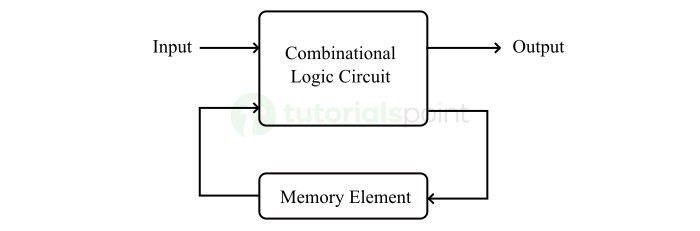
As shown in the figure, there are two main parts presents in the Mealy state machine. Those are combinational logic circuit and memory element. The memory element is useful to provide some part of previous outputs and present states as inputs to the combinational logic circuit.
Based on the present inputs and present states, the Mealy state machine produces outputs. Therefore, the outputs will be valid only at positive or negative transition of the clock signal.
State Diagram of Mealy State Machine
The state diagram of Mealy state machine is shown in the following figure.

In the above figure, there are three states, namely A, B and C. These states are labelled inside the circles and each circle corresponds to one state. State transitions between these states are represented with directed lines. Here, 0 / 0, 1 / 0 and 1 / 1 denote the input / output. In the above figure, there are two state transitions from each state based on the value of input.
In general, the number of states required in Mealy state machine is less than or equal to the number of states required in Moore state machine. There is an equivalent Moore state machine for each Mealy state machine.
Moore State Machine
A Finite State Machine is said to be a Moore state machine, if its outputs depend only on the present states.
The block diagram of the Moore state machine is shown in the following figure −
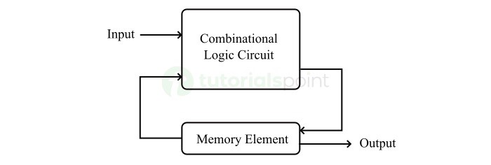
As shown in above figure, there are two parts presents in a Moore state machine. Those are combinational logic and memory. In this case, the present inputs and present states determine the next states. So, based on next states, Moore state machine produces the outputs. Therefore, the outputs will be valid only after transition of the state.
State Diagram of Moore State Machine
The state diagram of Moore state machine is shown in the following figure −
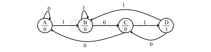
In the above figure, there are four states, namely A, B, C, and D. These states and the respective outputs are labelled inside the circles. Here, only the input value is labeled on each transition. In the above figure, there are two transitions from each state based on the value of input.
In general, the number of states required in Moore state machine is more than or equal to the number of states required in Mealy state machine. There is an equivalent Mealy state machine for each Moore state machine. So, based on the requirement we can use one of them.
Advantages of Finite State Machine
The Finite State Machines have several advantages in the field of digital electronics. All these advantages make them a crucial tool for modeling and implementing various digital systems. Some key advantages of Finite State Machines are listed below −
- Finite state machines provide a simple and systematic way to model and understand the behavior of digital systems with discrete finite states and transitions between them.
- Finite state machines support modular designs that help to breakdown the complex digital systems into smaller components. Each component of the finite state machine can represent a specific task of the entire system. This allows for easier design, testing, and maintenance.
- Finite state machines provide ease in terms of scalability that allows for addition of new states and transitions, and logics to the existing system without altering its fundamental structure or operation. This becomes essential when the system requirement evolve or expand.
- Fundamentally, finite state machines have a deterministic or predictable behavior. That means, we can easily determine the next state of the system from its current state and the inputs. This predictable behavior helps us to ensure the reliable and consistent operation of the system. It also makes the finite state machines best suited for real-time and safety-critical applications.
- Finite state machines are considered highly efficient in terms of both hardware and software implementations, as they require minimal hardware and software resources such as logic gates, memory, and other processing resources.
- Finite state machines support parallelism. This technology allows the occurrence of multiple states and state transitions simultaneously within the system. It also optimizes the performance and improves the responsiveness of the system.
- Finite state machines are versatile tools in the field of digital electronics and computer science, as they find their applications in various fields such as digital system design, control system design, software development, development of artificial intelligence, etc.
Applications of Finite State Machine
In the field of digital electronics and computer science, the finite state machines are used in various applications due to their ability to model sequential logic systems effectively. Here are some examples of applications of finite state machines −
- Finite state machines are commonly used in designing and implementation of different types of sequential logic circuits, such as digital counters, timers, control units, etc.
- Finite state machines are used in digital control systems to control and regulate the behavior of complex automated systems, like robots, industrial control and automation systems, etc.
- Finite state machines are used in the implementation of communication protocols like network protocols and state-based digital systems like data transmission and protocol converters.
- Finite state machines are also used in the field of software development to model and define the behavior of state-based systems in applications, to create user interfaces, to implement game mechanics, and to develop workflow management systems.
Conclusion
In conclusion, finite state machines are important and powerful tools used in the field of digital electronics to model, design, and analyze the behavior of state-based digital systems and synchronous sequential circuits.
Finite state machines allow engineers and system designers to design and implement efficient, reliable, and scalable systems that can handle complex state-based logics and processes in the field of digital electronics and computer engineering.
