 Data Structure
 Networking
 RDBMS
RDBMS Operating System
 Java
Java MS Excel
 iOS
iOS HTML
HTML CSS
CSS Android
 Python
 C Programming
 C++
C++ C#
C# MongoDB
 MySQL
MySQL Javascript
 PHP
PHP
- Selected Reading
- UPSC IAS Exams Notes
- Developer's Best Practices
- Questions and Answers
- Effective Resume Writing
- HR Interview Questions
- Computer Glossary
- Who is Who
Description of 8253 timer
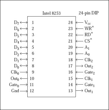
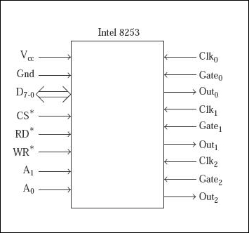
As a DIP package Intel 8253 is a 24-pin programmable IC available. IChas three counters which work independently and whose width is of16-bits. In addition, we have a control port to decide what is the mode of working of the three counters. The physical and functional pin diagrams of them are indicated below.

Fig.Diagram of 8253 pin based

Fig.Pin diagram functional
| Vcc and Gn |
These are the Power supply and ground pins which 8253 uses +5V as power supply |
| D7-0 |
For the communication of the processor there are eight functional pins |
| RD* |
This reads counter information it is active low pin |
| WR* |
Writes control information |
| CS* |
It selects the chip which is also active low pin |
| A1,A0 |
These are the address input pins. |
| CLK0 |
Clock input is provided for counter 0 |
| CLK1 |
Clock input is provided for counter 1 |
| CLK2 |
Clock input is provided for counter 2 |
| Gate0 |
Controls counter function 0 |
| Gate1 |
Controls function of counter 1 |
| Gate2 |
Controls function of counter 2 |
| Out0 |
Here counter 0 sends output |
| Out1 |
Here counter 1 sends output |
| Out2 |
Again counter 2 sends the output |

Advertisements
