
Article Categories
- All Categories
-
 Data Structure
-
 Networking
-
 RDBMS
RDBMS
-
 Operating System
-
 Java
Java
-
 MS Excel
-
 iOS
iOS
-
 HTML
HTML
-
 CSS
CSS
-
 Android
-
 Python
-
 C Programming
-
 C++
C++
-
 C#
C#
-
 MongoDB
-
 MySQL
MySQL
-
 Javascript
-
 PHP
PHP
-
 Economics & Finance
Deep sleep in Arduino
The equivalent of deep sleep in Arduino would be the Power Down mode, which consumes the least power out of all the sleep modes. While this has already been covered in another article, but for the sake of completeness, here’s a brief on the sleep modes in Arduino.
Arduino’s microcontroller, ATmega328P has 6 sleep modes, of which 5 are available with the avr/sleep.h library.
Idle mode
ADC Noise Reduction
Power-down
Power-save
Standby
Extended Standby
Each mode has different wake-up modes and different power consumption.
The Idle mode is easiest to wake up from and the Standby and Power down mode is the most difficult to wake up from (you can only wake up the module from the Standby mode using external interrupts or watchdog timer). The Power down mode is also the most power efficient sleep mode.
The TWI Address match refers to I2C or Wire Address match. The microcontroller can wake up through this way only when it is the I2C slave, and a master sends address corresponding to this microcontroller to wake it up). You are encouraged to go through the datasheet of ATmega328P to read up more about the sleep modes.
Now, you can directly work with the avr/sleep.h library and explore the sleep modes within Arduino. An example is given here.
However, as always happens, someone has taken the effort to create a library. The library is called Low-Power. It can be found on GitHub here.
It is not available in Library Manager of Arduino IDE. The way to install such libraries has been explained here.
Once you install this library, go to: File → Examples → Low-Power → Examples.
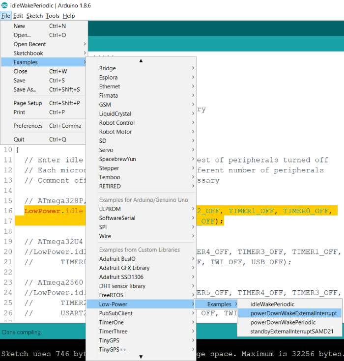
You will find two examples related to PowerDown mode. In one example, we wake up the Arduino using an external interrupt, while in another we use the WatchDog timer to wake up the Arduino.
Let’s walkthrough the external interrupt example. You are encouraged to go through the powerDownWakePeriodic example yourself (it is very straightforward) −
We include the LowPower library, and define pin 2 as the interrupt pin.
#include "LowPower.h"

// Use pin 2 as wake up pin
const int wakeUpPin = 2;
An empty handler is used for pin 2 interrupts.
void wakeUp()
{
   // Just a handler for the pin interrupt.
}
Within the setup, we just set the mode of pin2 to INPUT.
void setup()
{
   // Configure wake up pin as input.
   // This will consumes few uA of current.
   pinMode(wakeUpPin, INPUT);
}
Within the loop, we attach the interrupt handler to pin2, (Interrupt 0 corresponds to pin2. The neater way to do this would have been attachInterrupt(digitalPinToInterrupt(wakeUpPin), wakeUp, LOW)).
Thus, when a LOW signal is received on Pin 2, the interrupt is triggered, and the Arduino should wake up.
We then set the Arduino to sleep forever. We are disabling the ADC and the brown out detector. The brown out detector puts the ATmega328P chip in reset mode if the voltage on the Vcc line falls below a threshold. You can read more about it here.
By disabling the brown out detector, we ensure that any fluctuations in Vcc don’t reset the module. The ADC module anyway can’t wake up the microcontroller from the Power Down mode. The next lines after this will be executed only after the Arduino wakes up (i.e., after the interrupt).
void loop()
{
   // Allow wake up pin to trigger interrupt on low.
   attachInterrupt(0, wakeUp, LOW);

   // Enter power down state with ADC and BOD module disabled.
   // Wake up when wake up pin is low.
   LowPower.powerDown(SLEEP_FOREVER, ADC_OFF, BOD_OFF);

   // Disable external pin interrupt on wake up pin.
   detachInterrupt(0);

   // Do something here
   // Example: Read sensor, data logging, data transmission.
}
In order to test this, you simply need to send a low signal on pin 2, by shorting it to GND, once the Arduino is asleep. You can connect an Ammeter in series with the Arduino supply to verify that the current drops in the sleep mode.

9K+ Views
