
Article Categories
- All Categories
-
 Data Structure
-
 Networking
-
 RDBMS
RDBMS
-
 Operating System
-
 Java
Java
-
 MS Excel
-
 iOS
iOS
-
 HTML
HTML
-
 CSS
CSS
-
 Android
-
 Python
-
 C Programming
-
 C++
C++
-
 C#
C#
-
 MongoDB
-
 MySQL
MySQL
-
 Javascript
-
 PHP
PHP
-
 Economics & Finance
What is Nodal Analysis?
Nodal Analysis is a method for determining the branch currents in a circuit. In this method, one of the nodes is taken as the reference node. The potentials of all the nodes in the circuit are measured with respect to this reference node.
The nodal analysis is based on the Kirchhoff’s Current Law, which states that "the algebraic sum of incoming currents and outgoing currents at a node is equal to zero".
$$\mathrm{\sum\:\mathit{I}_{incoming}\:+\:\sum\:\mathit{I}_{outgoing}=0}$$
Node – A node is a point in a network where two or more circuit elements meet.
Junction – A junction is point where three or more circuit elements meet.
In the nodal analysis, we have to find the potentials at the junction points instead of nodes. The number of independent node-pair equations needed is one less than the number of junctions in the network. That is, if “n” is the number of independent node equations and “j” is the number of junctions, then,
$$\mathrm{n\:=\:\mathit{j}\:-\:1}$$
Explanation
Consider the circuit shown below. In the circuit, A, B, C and D are four nodes and node B and D are the junction points, where node D is taken as reference node. Hence,
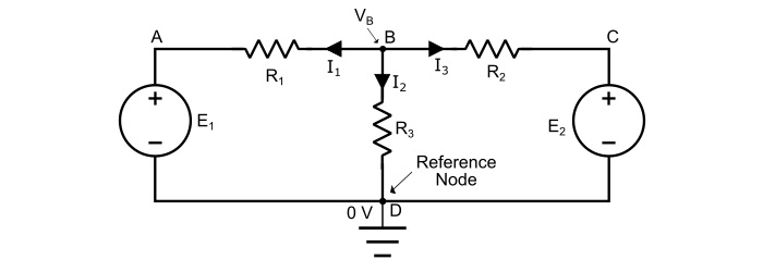
Assuming the voltage VB at the node B higher than all the other nodes of the circuit.
Applying KCl at the node B, we obtain,
$$\mathrm{\mathit{I}_{1}\:+\:\mathit{I}_{2}\:+\:\mathit{I}_{3}=0}\:\:\:…(1)$$
Now, by Ohm’s law, the branch currents are,
$$\mathrm{\mathit{I}_{1}=\frac{\mathit{V}_{B}\:-\mathit{E}_{1}\:-0}{\mathit{R}_{1}}=\frac{\mathit{V}_{B}\:-\:E_{1}}{\mathit{R}_{1}}}$$
$$\mathrm{\mathit{I}_{2}=\frac{\mathit{V}_{B}\:-\mathit{E}_{2}\:-0}{\mathit{R}_{2}}=\frac{\mathit{V}_{B}\:-\:E_{2}}{\mathit{R}_{2}}}$$
And,
$$\mathrm{\mathit{I}_{3}=\frac{\mathit{V}_{B}\:-0}{\mathit{R}_{3}}=\frac{\mathit{V}_{B}}{\mathit{R}_{3}}}$$
Substituting the values of I1, I2 and I3 in the equation (1), we get,
$$\mathrm{\frac{\mathit{V}_{B}\:-\mathit{E}_{1}}{\mathit{R}_{1}}+\frac{\mathit{V}_{B}\:-E_{2}}{\mathit{R}_{2}}+\frac{\mathit{V}_{B}}{\mathit{R}_{3}}=0}\:\:\:…(2)$$
The voltage VB at node B can be obtained by solving the equation (2). As, the emfs, E1, E2 and resistance values are known. Thus, we can determine the values branch currents.
Numerical Example
Find the currents in the various branches of the circuit in figure given below by nodal analysis.
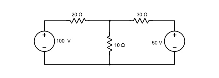
Solution
Mark the currents in various branches as shown in the circuit diagram. If the value of any current comes out to be negative in the solution, it means that actual direction of the current is opposite to that of assumed. Take point B as the reference node. Thus,
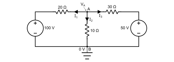
Applying KCL at node A,
$$\mathrm{\mathit{I}_{1}\:+\:\mathit{I}_{2}\:+\:\mathit{I}_{3}=0}\:\:\:…(3)$$
By Ohm’s law,
$$\mathrm{\mathit{I}_{1}=\frac{\mathit{V}_{A}-100}{20}}$$
$$\mathrm{\mathit{I}_{2}=\frac{\mathit{V}_{A}}{10}}$$
And
$$\mathrm{\mathit{I}_{3}=\frac{\mathit{V}_{A}-50}{30}}$$
Substituting the values of I1, I2 and I3 in the equation (3), we obtain,
$$\mathrm{\frac{\mathit{V}_{A}-100}{20}+\frac{\mathit{V}_{A}}{10}+\frac{\mathit{V}_{A}-50}{30}=0}$$
$$\mathrm{\Rightarrow\frac{3(\mathit{V}_{A}-100)+6\mathit{V}_{A}+2(\mathit{V}_{A}-50)}{60}=0}$$
$$\mathrm{\Rightarrow\:3\mathit{V}_{A}-300+6\mathit{V}_{A}+2\mathit{V}_{A}-100=0}$$
$$\mathrm{\Rightarrow\:11\mathit{V}_{A}=400}$$
$$\mathrm{\mathit{V}_{A}=\frac{400}{11}=36.36\mathit{V}}$$
Hence, the voltage at the node A is equal to 36.36 V, therefore the branch current are,
$$\mathrm{Current\:\mathit{I}_{1}=\frac{\mathit{V}_{A}-100}{20}=\frac{36.36-100}{20}=-3.182\:A}$$
$$\mathrm{Current\:\mathit{I}_{2}=\frac{\mathit{V}_{A}}{20}=\frac{36.36}{20}=3.636\:A}$$
$$\mathrm{Current\:\mathit{I}_{3}=\frac{\mathit{V}_{A}-50}{30}=\frac{36.36-50}{30}=0.455\:A}$$
The negative sign for currents I1 and I33 shows that actual direction of currents is opposite to that of assumed.

2K+ Views
