- WebGL - Home
- WebGL - Introduction
- WebGL - Html5 Canvas Overview
- WebGL - Basics
- WebGL - Graphics Pipeline
- WebGL - Sample Application
- WebGL - Context
- WebGL - Geometry
- WebGL - Shaders
- Associating Attributes & Buffer Objects
- WebGL - Drawing a Model
- WebGL Examples
- WebGL - Drawing Points
- WebGL - Drawing a Triangle
- WebGL - Modes of Drawing
- WebGL - Drawing a Quad
- WebGL - Colors
- WebGL - Translation
- WebGL - Scaling
- WebGL - Rotation
- WebGL - Cube Rotation
- WebGL - Interactive Cube
- WebGL Useful Resources
- WebGL - Quick Guide
- WebGL - Useful Resources
- WebGL - Discussion
WebGL - Basics
WebGL is mostly a low-level rasterization API rather than a 3D API. To draw an image using WebGL, you have to pass a vector representing the image. It then converts the given vector into pixel format using OpenGL SL and displays the image on the screen. Writing a WebGL application involves a set of steps which we would be explaining in this chapter.
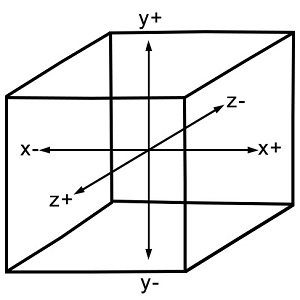
WebGL - Coordinate System
Just like any other 3D system, you will have x, y and z axes in WebGL, where the z axis signifies depth. The coordinates in WebGL are restricted to (1, 1, 1) and (-1, -1, - 1). It means − if you consider the screen projecting WebGL graphics as a cube, then one corner of the cube will be (1, 1, 1) and the opposite corner will be (-1, -1, -1). WebGL wont display anything that is drawn beyond these boundaries.
The following diagram depicts the WebGL coordinate system. The z-axis signifies depth. A positive value of z indicates that the object is near the screen/viewer, whereas a negative value of z indicates that the object is away from the screen. Likewise, a positive value of x indicates that the object is to the right side of the screen and a negative value indicates the object is to the left side. Similarly, positive and negative values of y indicate whether the object is at the top or at the bottom portion of the screen.
WebGL Graphics
After getting the WebGL context of the canvas object, you can start drawing graphical elements using WebGL API in JavaScript.
Here are some fundamental terms you need to know before starting with WebGL.
Vertices
Generally, to draw objects such as a polygon, we mark the points on the plane and join them to form a desired polygon. A vertex is a point which defines the conjunction of the edges of a 3D object. It is represented by three floating point values each representing x, y, z axes respectively.
Example
In the following example, we are drawing a triangle with the following vertices − (0.5, 0.5), (-0.5, 0.5), (-0.5, -0.5).
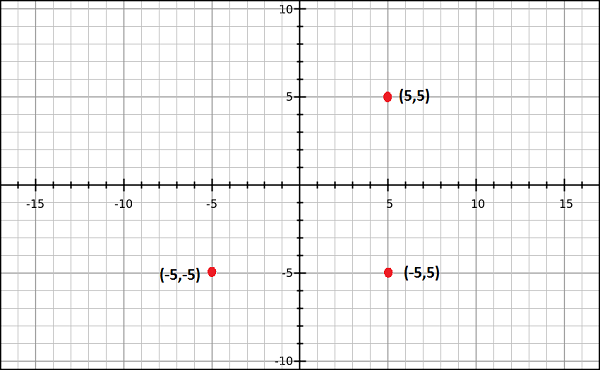
Note − We have to store these vertices manually using JavaScript arrays and pass them to the WebGL rendering pipeline using vertex buffer.
Indices
In WebGL, numerical values are used to identify the vertices. These numerical values are known as indices. These indices are used to draw meshes in WebGL.
Note − Just like vertices, we store the indices using JavaScript arrays and pass them to WebGL rendering pipeline using index buffer.
Arrays
Unlike OpenGL and JoGL, there are no predefined methods in WebGL to render the vertices directly. We have to store them manually using JavaScript arrays.
Example
var vertices = [ 0.5, 0.5, 0.1,-0.5, 0.5,-0.5]
Buffers
Buffers are the memory areas of WebGL that hold the data. There are various buffers namely, drawing buffer, frame buffer, vetex buffer, and index buffer. The vertex buffer and index buffer are used to describe and process the geometry of the model.
Vertex buffer objects store data about the vertices, while Index buffer objects store data about the indices. After storing the vertices into arrays, we pass them to WegGL graphics pipeline using these Buffer objects.
Frame buffer is a portion of graphics memory that hold the scene data. This buffer contains details such as width and height of the surface (in pixels), color of each pixel, depth and stencil buffers.
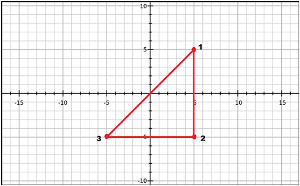
Mesh
To draw 2D or 3D objects, the WebGL API provides two methods namely, drawArrays() and drawElements(). These two methods accept a parameter called mode using which you can select the object you want to draw. The options provided by this field are restricted to points, lines, and triangles.
To draw a 3D object using these two methods, we have to construct one or more primitive polygons using points, lines, or triangles. Thereafter, using those primitive polygons, we can form a mesh.
A 3D object drawn using primitive polygons is called a mesh. WebGL offers several ways to draw 3D graphical objects, however users normally prefer to draw a mesh.
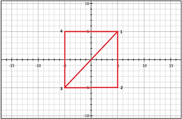
Example
In the following example, you can observe that we have drawn a square using two triangles→ {1, 2, 3} and {4, 1, 3}.
Shader Programs
We normally use triangles to construct meshes. Since WebGL uses GPU accelerated computing, the information about these triangles should be transferred from CPU to GPU which takes a lot of communication overhead.
WebGL provides a solution to reduce the communication overhead. Since it uses ES SL (Embedded System Shader Language) that runs on GPU, we write all the required programs to draw graphical elements on the client system using shader programs (the programs which we write using OpenGL ES Shading Language / GLSL).
These shaders are the programs for GPU and the language used to write shader programs is GLSL. In these shaders, we define exactly how vertices, transformations, materials, lights, and camera interact with one another to create a particular image.
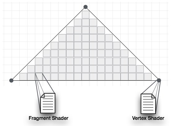
In short, it is a snippet that implements algorithms to get pixels for a mesh. We will discuss more about shaders in later chapters. There are two types of shaders − Vertex Shader and Fragment Shader.
Vertex Shader
Vertext shader is the program code called on every vertex. It is used to transform (move) the geometry (ex: triangle) from one place to another. It handles the data of each vertex (per-vertex data) such as vertex coordinates, normals, colors, and texture coordinates.
In the ES GL code of vertex shader, programmers have to define attributes to handle the data. These attributes point to a Vertex Buffer Object written in JavaScript.
The following tasks can be performed using vertex shaders −
- Vertex transformation
- Normal transformation and normalization
- Texture coordinate generation
- Texture coordinate transformation
- Lighting
- Color material application
Fragment Shader(Pixel Shader)
A mesh is formed by multiple triangles, and the surface of each of the triangles is known as a fragment. Fragment shader is the code that runs on all pixels of every fragment. It is written to calculate and fill the color on individual pixels.
The following tasks can be performed using Fragment shaders −
- Operations on interpolated values
- Texture access
- Texture application
- Fog
- Color sum
OpenGL ES SL Variables
The full form of OpenGL ES SL is OpenGL Embedded System Shading Language. To handle the data in the shader programs, ES SL provides three types of variables. They are as follows −
Attributes − These variables hold the input values of the vertex shader program. Attributes point to the vertex buffer objects that contains per-vertex data. Each time the vertex shader is invoked, the attributes point to VBO of different vertices.
Uniforms − These variables hold the input data that is common for both vertex and fragment shaders, such as light position, texture coordinates, and color.
Varyings − These variables are used to pass the data from the vertex shader to the fragment shader.
With this much basics, we will now move on to discuss the Graphics Pipeline.
