- VLSI Design - Home
- VLSI Design - Digital System
- VLSI Design - FPGA Technology
- VLSI Design - MOS Transistor
- VLSI Design - MOS Inverter
- Combinational MOS Logic Circuits
- Sequential MOS Logic Circuits
- VLSI Design Useful Resources
- VLSI Design - Quick Guide
- VLSI Design - Useful Resources
- VLSI Design - Discussion
VLSI Design - VHDL Introduction
VHDL stands for very high-speed integrated circuit hardware description language. It is a programming language used to model a digital system by dataflow, behavioral and structural style of modeling. This language was first introduced in 1981 for the department of Defense (DoD) under the VHSIC program.
Describing a Design
In VHDL an entity is used to describe a hardware module. An entity can be described using,
- Entity declaration
- Architecture
- Configuration
- Package declaration
- Package body
Lets see what are these?
Entity Declaration
It defines the names, input output signals and modes of a hardware module.
Syntax −
entity entity_name is
   Port declaration;
end entity_name;
An entity declaration should start with entity and end with end keywords. The direction will be input, output or inout.
| In | Port can be read |
| Out | Port can be written |
| Inout | Port can be read and written |
| Buffer | Port can be read and written, it can have only one source. |
Architecture −
Architecture can be described using structural, dataflow, behavioral or mixed style.
Syntax −
architecture architecture_name of entity_name
architecture_declarative_part;

begin
   Statements;
end architecture_name;
Here, we should specify the entity name for which we are writing the architecture body. The architecture statements should be inside the begin and nd keyword. Architecture declarative part may contain variables, constants, or component declaration.
Data Flow Modeling
In this modeling style, the flow of data through the entity is expressed using concurrent (parallel) signal. The concurrent statements in VHDL are WHEN and GENERATE.
Besides them, assignments using only operators (AND, NOT, +, *, sll, etc.) can also be used to construct code.
Finally, a special kind of assignment, called BLOCK, can also be employed in this kind of code.
In concurrent code, the following can be used −
- Operators
- The WHEN statement (WHEN/ELSE or WITH/SELECT/WHEN);
- The GENERATE statement;
- The BLOCK statement
Behavioral Modeling
In this modeling style, the behavior of an entity as set of statements is executed sequentially in the specified order. Only statements placed inside a PROCESS, FUNCTION, or PROCEDURE are sequential.
PROCESSES, FUNCTIONS, and PROCEDURES are the only sections of code that are executed sequentially.
However, as a whole, any of these blocks is still concurrent with any other statements placed outside it.
One important aspect of behavior code is that it is not limited to sequential logic. Indeed, with it, we can build sequential circuits as well as combinational circuits.
The behavior statements are IF, WAIT, CASE, and LOOP. VARIABLES are also restricted and they are supposed to be used in sequential code only. VARIABLE can never be global, so its value cannot be passed out directly.
Structural Modeling
In this modeling, an entity is described as a set of interconnected components. A component instantiation statement is a concurrent statement. Therefore, the order of these statements is not important. The structural style of modeling describes only an interconnection of components (viewed as black boxes), without implying any behavior of the components themselves nor of the entity that they collectively represent.
In Structural modeling, architecture body is composed of two parts − the declarative part (before the keyword begin) and the statement part (after the keyword begin).
Logic Operation AND GATE
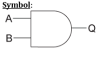
| X | Y | Z |
|---|---|---|
| 0 | 0 | 0 |
| 0 | 1 | 0 |
| 1 | 0 | 0 |
| 1 | 1 | 1 |
VHDL Code:
Library ieee;
use ieee.std_logic_1164.all;

entity and1 is
   port(x,y:in bit ; z:out bit);
end and1;

architecture virat of and1 is
begin
   z<=x and y;
end virat;
Waveforms

Logic Operation OR Gate
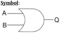
| X | Y | Z |
|---|---|---|
| 0 | 0 | 0 |
| 0 | 1 | 1 |
| 1 | 0 | 1 |
| 1 | 1 | 1 |
VHDL Code:
Library ieee;
use ieee.std_logic_1164.all;

entity or1 is
   port(x,y:in bit ; z:out bit);
end or1;

architecture virat of or1 is
begin
   z<=x or y;
end virat;
Waveforms
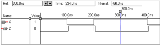
Logic Operation NOT Gate
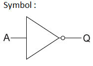
| X | Y |
|---|---|
| 0 | 1 |
| 1 | 0 |
VHDL Code:

Library ieee;
use ieee.std_logic_1164.all;

entity not1 is
   port(x:in bit ; y:out bit);
end not1;

architecture virat of not1 is
begin
   y<=not x;
end virat;
Waveforms
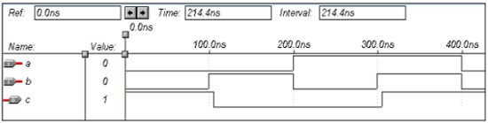
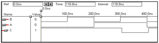
Logic Operation NAND Gate
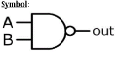
| X | Y | z |
|---|---|---|
| 0 | 0 | 1 |
| 0 | 1 | 1 |
| 1 | 0 | 1 |
| 1 | 1 | 0 |
VHDL Code:

Library ieee;
use ieee.std_logic_1164.all;

entity nand1 is
   port(a,b:in bit ; c:out bit);
end nand1;

architecture virat of nand1 is
begin
   c<=a nand b;
end virat;
Waveforms
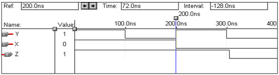
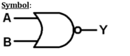
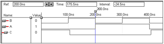
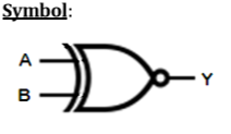
Logic Operation NOR Gate
| X | Y | z |
|---|---|---|
| 0 | 0 | 1 |
| 0 | 1 | 0 |
| 1 | 0 | 0 |
| 1 | 1 | 0 |
VHDL Code:

Library ieee;
use ieee.std_logic_1164.all;

entity nor1 is
   port(a,b:in bit ; c:out bit);
end nor1;

architecture virat of nor1 is
begin
   c<=a nor b;
end virat;
Waveforms
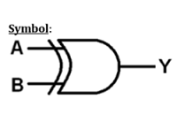
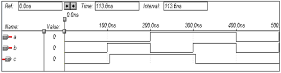
Logic Operation XOR Gate
| X | Y | Z |
|---|---|---|
| 0 | 0 | 1 |
| 0 | 1 | 1 |
| 1 | 0 | 1 |
| 1 | 1 | 0 |
VHDL Code:

Library ieee;
use ieee.std_logic_1164.all;

entity xor1 is
   port(a,b:in bit ; c:out bit);
end xor1;

architecture virat of xor1 is
begin
   c<=a xor b;
end virat;
Waveforms
Logic Operation X-NOR Gate
| X | Y | Z |
|---|---|---|
| 0 | 0 | 1 |
| 0 | 1 | 1 |
| 1 | 0 | 1 |
| 1 | 1 | 0 |
VHDL Code:

Library ieee;
use ieee.std_logic_1164.all;

entity xnor1 is
   port(a,b:in bit ; c:out bit);
end xnor1;

architecture virat of xnor1 is
begin
   c<=not(a xor b);
end virat;
Waveforms